This section contains the user guides for the following tools: Block JIG Generator, Compare GDSII, Gerber to PCB,
Make Board Paneling, Metal Mask Manager, Mounting Data Extractor, Mounting Emulator, Router-Machine JIG Generator,
Solder Quantity Calculator, Soldering Pallet, Test Point Location Generator, and Underfill.
This section contains the user guides for the following tools: BOM, CAM, Component Arrangement Plan, CP, Golden Sample,
Logic, PCB, Redmark+, and Worksheet Planner.
This item tracks the voltage and signal lines in the circuit, calculates the voltage value of each net, and checks
whether the all resistor connected to the net is within the allowable voltage range.
This item tracks the voltage and signal lines in the circuit, calculates the voltage value of each net, and checks
whether the all capacitor connected to the net is within the allowable voltage range.
This item tracks the voltage and signal lines in the circuit, calculates the voltage value of each net, and checks
whether the all diode connected to the net is within the allowable voltage range.
This item tracks the voltage and signal lines in the circuit, calculates the voltage value of each net, and checks
whether all varistor connected to the net is within the allowable voltage range.
This item tracks the voltage and signal lines in the circuit, calculates the voltage value of each net, and checks
whether all Transistor connected to the net is within the allowable voltage range.
This item tracks the voltage and signal lines in the circuit, calculates the voltage value of each net, and checks
whether all MOSFET connected to the net is within the allowable voltage range.
This item tracks the voltage and signal lines in the circuit, calculates the voltage value of each net, and checks
whether the all photo coupler connected to the net is within the allowable voltage range.
This item tracks the voltage and signal lines in the circuit, calculates the voltage value of each net, and checks
whether the all linear regulator connected to the net is within the allowable voltage range.
This item tracks the voltage and signal lines in the circuit, calculates the voltage value of each net, and checks
whether the all general IC connected to the net is within the allowable voltage range.
This item tracks the voltage and signal lines in the circuit, calculates the voltage value of each net, and checks
whether the all fuse connected to the net is within the allowable voltage range.
This item tracks the voltage and signal lines in the circuit, calculates the voltage value of each net, and checks
whether the all LED connected to the net is within the allowable voltage range.
This item tracks the voltage and signal lines in the circuit, calculates the voltage value of each net, and checks
whether the all coil connected to the net is within the allowable voltage range.
This item tracks the voltage and signal lines in the circuit, calculates the voltage value of each net, and checks
whether the all polymer PTC connected to the net is within the allowable voltage range.
The transient stress test item uses the SPICE Engine, it makes a SPICE net list, finds the node voltage, and checks
whether all passive components connected to the net are within the allowable voltage range.
To perform stress test, all necessary properties of all components should be set up.
If the property of every component is not included in the schematic, the fully
defined property database can be loaded from outside.
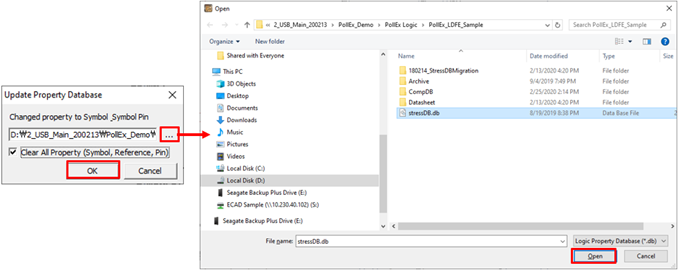
Upon selecting Tools/Property Database Import menu, the Update
Property Database dialog will be open.
Click ... to open the Explorer
dialog.
Navigate and select property database file (*.db), click
Open to close the Explorer
dialog.
If you select Clear All Property (Symbol, Reference, Pin) option, all exist
property for symbol, reference and pin will be erased, and new property data
will be written.
Click OK to close the Update Property
Database dialog.