Photo Coupler
This item tracks the voltage and signal lines in the circuit, calculates the voltage value of each net, and checks whether the all photo coupler connected to the net is within the allowable voltage range.
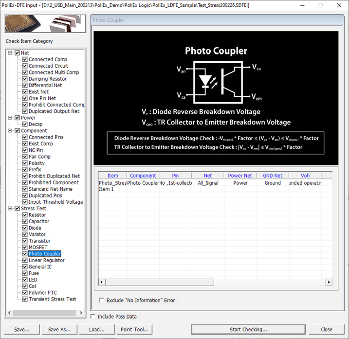
Figure 1.
- Component: Select Photo Coupler component group to be checked.
- Pin: Assign
pin information of Photo Coupler. You can assign pin number using Pin Number
or Pin Property which contain pin number information.
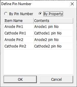
Figure 2. - Net: Select net group to which Photo Coupler components are connected.
- Power Net: Select power net group to which Photo Coupler components are connected.
- GND Net: Select ground net group to which Photo Coupler components are connected.
- Voh: Set the output high voltage (Voh) of driver pin. You can set this by entering the value directly or select the property name which contain voh value.
- Vol: Set the output low voltage (Vol) of driver pin. You can set this by entering the value directly or select the property name which contain vol value.
- Diode
Reverse Voltage Check: Set the allowable reverse voltage of diode of this
component. You can set this by entering the allowable value directly or
select the property name which contain allowable reverse voltage value. User
can also assign tolerance of this check.
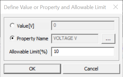
Figure 3. - TR Vce
Check: Set the allowable Vce voltage of transistor of this component. You
can set this by entering the allowable value directly or select the property
name which contain allowable Vce value. You can also assign tolerance of
this check.
Figure 4.
Stress Test Option
Set whether passive components are considered short or open when navigating signals and power lines.
-
Double-click the empty field to open the Stress Test
Option dialog.
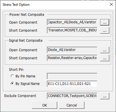
Figure 5. -
Power Net Composite Section: In this step, we declare the component to be
processed short and the component to be opened during power trace navigation.
Since Stress Test is a DC level test, the capacitor is considered as open and
inductor is considered as short. And normally the resistor is considered as
open, because the current of power net is so big that the IR-Drop can’t be
ignored. Since TR and FET are used as switching components, they are regarded as
short when voltage navigating.
-
Short Component: Select the component group to be regarded as short
when power trace navigating.
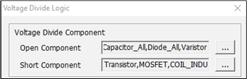
Figure 6.
-
Short Component: Select the component group to be regarded as short
when power trace navigating.
-
Signal Net Composite Section: In this section, we declare the component to be
processed short and the component to be opened during signal trace navigation.
Since Stress Test is a DC level test, the capacitor is considered as open and
inductor is considered as short. And normally the resistor is considered as
short, because the current of signal net is so small that the IR-Drop can be
ignored.
- Open Component: Select the component group to be regarded as short when signal trace navigating.
- Short Component: Select the component group to be regarded as short when signal trace navigating.
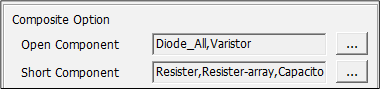
Figure 7. -
Short Pin Section: TR or FET is a device with three pins, so it needs
information about pins connected to each other during short processing.
-
By Signal Name: Declare pin paring information as signal name. If there
is more than one condition, the separator “,” is used.
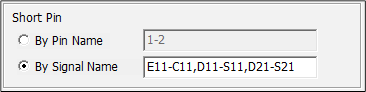
Figure 8.
-
By Signal Name: Declare pin paring information as signal name. If there
is more than one condition, the separator “,” is used.
-
Exclude Component: Select component group to be excluded during test.

Figure 9.