Impedance
This item analyzes and checks single-ended and differential impedance of target nets.
This item checks the followings:
- Check the single-ended impedance.
- Check the differential impedance (Characteristic, Zdiff,
Zcommon).
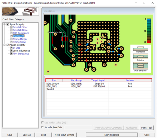
Figure 1. - Item: Enter sub item name. User can enter arbitrary name.
- Net Group: Select target net groups to be tested. Allow multiple net groups.
- Target Impedance: You can assign required impedance for main area and break
in area. You can also set tolerance (%) for each main area and break in
area.
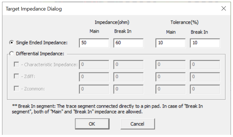
Figure 2.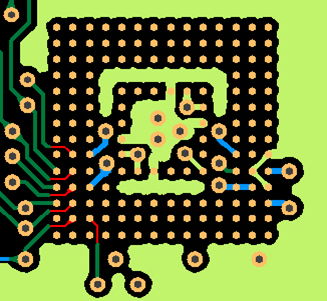
Figure 3. Break-In/Out Definition - Options: You can assign PIN/VIA Escape length and other options.
- Pin Escape: Enter a radius of circular region around pins to be excluded for the rule check.
- Via Escape: Enter a radius of circular region around vias to be excluded for the rule check.
- Ignore trace shorter than: the trace shorter than this length will be ignored.
- Break-In range (COC+distance): Enter Break-In range value. The break-in
range refers to the sum of the distance within the COC line and the user
defined distance outside of COC line.
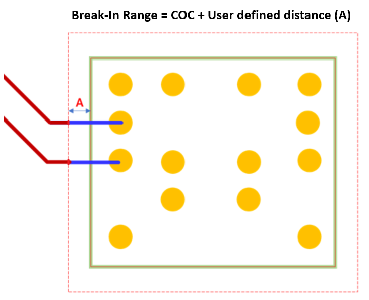
Figure 4. - Ideal: Consider the reference plane as ideal plane during analysis. If this option is used, the reference is determined using the settings of the PCB stackup.
- Real: Analysis proceed by reflecting the shape of the reference plane. If this option is used, the net with net type "Ground" is regarded as the reference plane.