Flight time
This item analyzes and check the time it takes for the signal to pass from the driver to the receiver.
This item checks following:
- The time it takes for the signal to pass from the driver to the receiver.
- Two types of measurement standard - Pin to Pin, Die to Die.
- Flight time is used interchangeably with propagation delay.
- It used to limit the trace length considering losses.
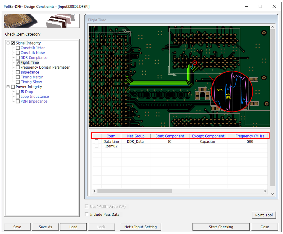
Figure 1.
- Item: Sub item name. User can enter arbitrary.
- Net Group: Select target net group to be tested. Allow multiple net groups.
- Except Component: Select the component to exclude from timing measurement, for example, a test point.
- Frequency (MHz): Setup operating frequency.
- Vth (Threshold Voltage): Voltage reference for measurement purpose.
- When default voltage is selected, the following priority is used to
determine the simulation model parameter.
- Vref (Vmeasure)
- (Vih + Vil)/2
- (Min/Max of waveform)/2
- Use user defined voltage: Enter the threshold voltage directly from user.
- When default voltage is selected, the following priority is used to
determine the simulation model parameter.
- Flight Time (ps): Enter allowable max Flight time.
- Tolerance (%): Enter allowable tolerance of maximum Flight time.
- Analyze Options Dialog: You can assign driver/receiver buffer simulation
model, driving strength of driver and other simulation parameters.
- Use pre-defined buffer model: The buffer model set in the electrical pin part of UPE is used as default. The user cannot change the buffer model here.
- Use user defined buffer model: You can assign simulation buffer model.
- Transient Analysis Parameters:
- Analysis Type: Click the desired analysis type. Editable setting parameters will be shown.
- Simulation time: End time of the SPICE transient analysis.
- Signaling time: Input Signal having pulse period (2ns) will be excited to the net until the time assigned here.
- Default Device Models: Use the default device model embedded in PollEx.
- Measure Base:
- Die to Die: Perform normal waveform analysis. Measure the time difference between the driver and the receiver waveform in the result.
- Pin to Pin: Add probes to the driver/receiver pins in the topology and perform waveform analysis. Measure the time difference between the probes at the driver end and the probes at the receiver end in the result.