If you selected a design space before invoking the tool, symmetry planes are
automatically applied to that design space. Otherwise, click on a design space
to select it.
A microdialog appears, and a set of three orthogonal red planes appear
on the selected design space indicating that symmetry planes have been applied
in three directions.
Click on a plane to deactivate it.
Symmetry planes toggle on and off with each successive click. Active
symmetry planes are shown in red and disabled planes in gray.
Right-click and mouse through the check mark to exit, or double-right-click.
Microdialog Options
Double-click a shape control to edit it and access the microdialog
options.
Icon
Description
Apply Symmetry and Cyclic Repetition
Click to convert to a different type of shape control.
Translate or rotate the shape control.
Align a shape control to a design space after moving it. By default,
the symmetry planes are positioned and aligned to capture the natural
shape and orientation of the design space, however it is oriented in
space.
Align a shape control to the global axes.
Symmetric Examples
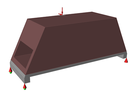
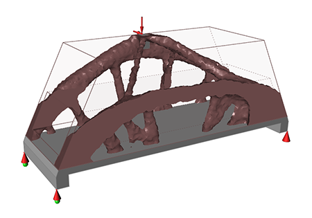
When you use an asymmetric design space or apply asymmetric load cases and then run
an optimization, you usually generate an asymmetric shape, as shown below: Figure 1. An asymmetric load case Figure 2. Optimization of an asymmetric load case
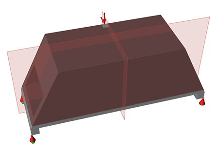
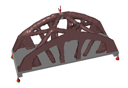
You can generate symmetric shapes, even under asymmetric conditions, by defining
symmetry planes in the design space. Below, two symmetry planes have been applied to
ensure that the resulting optimized shape is symmetric. You don't always get a
perfectly symmetric shape, but you do get a result that is very nearly
symmetric.Figure 3. An asymmetric load case with symmetry planes applied Figure 4. Optimization of an asymmetric load case with symmetry planes
applied You can apply up to three symmetry planes to a design space. The planes are
always orthogonal to one another and can be rotated as a group in any orientation
relative to the design space.