
Cyclic Symmetric
Use the Cyclic Symmetric tool on the Structure ribbon to apply cyclic symmetric repetition to a design space.
Cyclic symmetric repetitions are valid for optimization but not analysis.
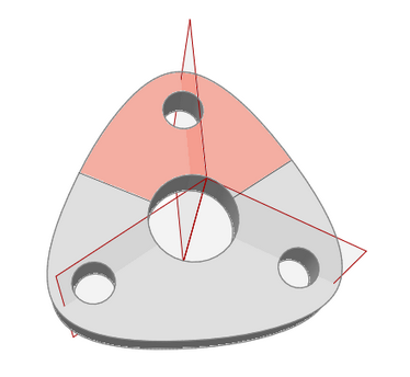
To enforce cyclic symmetric repetition on a design space, you specify a center line and the number of repetitions to create within a 360 revolution. Red edges appear on cyclic repetition planes to indicate symmetric sectors and black edges to indicate asymmetric sectors, as shown above. You won't usually generate perfectly cyclic shapes, but you will get nearly cyclic shapes.
Take note not to confuse the Cyclic Symmetric tool with the Symmetric tool. The latter forces an entire design space to be symmetric about a plane, while cyclic symmetric repetition forces each individual sector within a cyclic design space to be self-symmetric about the red radial planes, as illustrated above. You are prevented from applying a cyclic constraint and a symmetric constraint simultaneously to one design space.
Apply Cyclic Symmetric Repetition
Select a design space and the number of cyclic symmetric sectors.
-
On the Structure ribbon, select the Symmetric tool on
the Shape Controls icon.

Tip: To find and open a tool, press Ctrl+F. For more information, see Find and Search for Tools. -
Click the Cyclic Symmetric tool on the secondary
ribbon.

-
If you selected a design space before invoking the tool, cyclic symmetric
repetitions are automatically applied to that design space. Otherwise, click on
a design space to apply a cyclic symmetric constraint.
A microdialog and a set of three red radial planes appear.
-
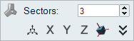
Specify the number of Sectors in the text field of the
microdialog.
- Right-click and mouse through the check mark to exit, or double-right-click.
Microdialog Options
Double-click a shape control to edit it and access the microdialog options.
| Icon | Description |
|---|---|
| Apply Symmetry and Cyclic Repetition | Click to convert to a different type of shape control. |
| Sectors | Enter the number of cyclic symmetric sectors. |
| Translate or rotate the shape control. | |
| Align the radial planes to the global x, y, or z direction. | |
| Align a shape control to a design space after moving it. By default, the radial planes are positioned and aligned to capture the natural shape and orientation of the design space, however it is oriented in space. | |
| Click to manually enter the x, y, z components of the direction vector. |