
Spot Welds
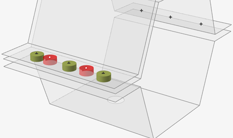
Spot welds connect parts together by welding them at specific locations.
- Clicking a location on the model where multiple parts are in close proximity (based on the search distance)
- Selecting point parts on an Inspire or CAD model
- Importing parts from a .csv file, where spot welds will be created
automaticallyNote: You can use the provided Sample CSV File to format .csv files, or you can use to import a point-only .csv file.
Click the satellite icon ![]() that
appears when you hover over the Spot Welds tool to view a list of
all spot welds.
that
appears when you hover over the Spot Welds tool to view a list of
all spot welds.
- When parts are spot welded together, the contacts between the surfaces are converted from Bonded to No Contact.
- Spot welds can be applied to either surfaces or solids. Use the SimSolid solver for solids and the OptiStruct solver for surfaces. SimSolid only supports 2T welds. The solver can be set in the Preferences under .
Create Spot Welds
Select the tool, then click on the model to create a spot weld.
-
On the Structure ribbon, select the Spot Welds
tool.

Tip: To find and open a tool, press Ctrl+F. For more information, see Find and Search for Tools. -
Choose a group from the Name dropdown or click
 to create a new group
for creating spot welds.
to create a new group
for creating spot welds.
-
Select the parts and points you want to weld.
- Click Displayed in the Spot Welds guide panel to search all displayed parts, not only selected parts.
- Click the Select collector in the Spot Welds
guide panel and click the parts you want to weld.

-
Select the Point(s) collector and define where to place
the spot welds:
- Select imprinted points.

- Click any location on the weld part.
 Tip: You can use the Spot Welds Table to import weld from a CSV file. For more information, see Spot Welds Table.
The selected welds are previewed automatically.
- Select imprinted points.
- Enter the Tolerance that determines which parts are included in the spot weld.
- Enter the Diameter of the spot welds.
- Optional:
Select the Skip collector and click any welds you want
to exclude from the spot-weld process. Skipped welds are displayed in red.
- Right-click and mouse through the check mark to exit, or double-right-click. A new weld group is created.
- If the Parts Select collector is selected on the guide bar and there are no spot welds selected, selecting a part will remove the part from all spot welds in the model.
- Spot welds can be organized into groups using the Spot Welds table or the Model Browser. Once created, you can move them between groups, but each spot weld can only be in one group.
- If you create a part that contains only points, then select this part in the Model Browser with the Spot Welds tool open; it will create spot welds at all of the points.
Spot Welds Table
The Spot Welds table lists all of the spot welds in your model. It can be used to change the weld diameter and assigned material or to import/export designated spot weld points in .csv format.
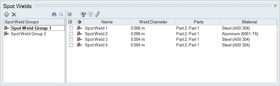
The table data can be edited with the following actions:
| To | Do this |
|---|---|
| Rename a spot weld | Select the cell in the table and then click again to make the field editable. |
| Change the material | Select the cell in the table and then select a different option from the list. |
| Sort a column | Click the column header. Click repeatedly to toggle between ascending and descending order. |
| Add or remove columns | Right-click on a column header. |
| Create a spot weld group | Click the  icon. icon. |
| Move a spot weld to a different group | Select the check box next to the spot weld, then right-click and
select Move to... from the context menu. Tip: Drag
a spot weld to a group to move it quickly. |
| Import points where spot welds will be created automatically | First, create a .csv file following the template.
|
| Export points where spot welds are located in the model |
|
Sample CSV File
When creating a .csv file for importing points for spot welds, use this sample as a template.
Altair Inspire 20xx build xxxxx
unit: MKS ( m kg N s) [ Length: m ]
Spot Welds
Group Name,Name,X-Pos,Y_Pos,Z_Pos,Layers,Diameter
62110,Spot Weld 2735,-0.520911,3.583000,0.208003,2T,0.006000
62110,Spot Weld 2736,-0.520911,3.557000,0.208003,2T,0.00600
Mouse Controls and Keyboard Shortcuts
| To | Do this |
|---|---|
| Select multiple points | Hold down the Ctrl key and left-click, or use box selection to create welds at all selected points. |
| Select surface parts to include | Hold down the Ctrl key and left-click a part to add it to or remove it from the spot weld. |
| Deselect all spot welds | Left-click on an empty space in the modeling window. |
| Delete a spot weld | Select a spot weld and press Delete. |
| Exit the tool | Right-click and mouse through the check mark to exit, or double-right-click. |