
Contacts
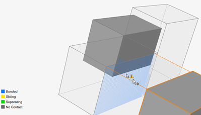
You can define Contacts as bonded, sliding, separating, or no contact. When running SimSolid analysis, you can have a mixed case of sliding and separating contacts. When running OptiStruct analysis, all contacts must be either sliding or separating.
This tool detects possible contacts in your model. If contacts aren't found, you can manually increase the search distance to find contacts between parts.
Defining Surface Contacts
Find neighboring surfaces and designate whether they should be bonded, sliding, separating, or have no contact.
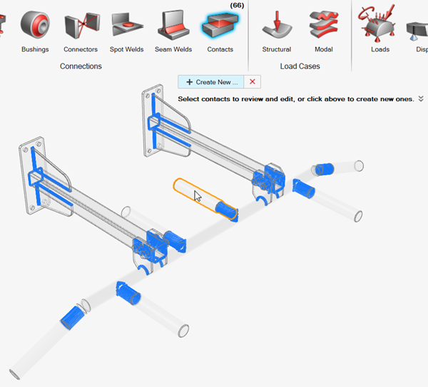
If you're opening an .stmod file with contacts defined, a guide bar is displayed. You can click Create New to create new contacts, or you can select existing contacts to review and edit them.
- If no contacts exist in a model, you'll be prompted to create them when running analysis. Use the Contact Type for Maintain and Find dropdown in to select the type of contact that is created.
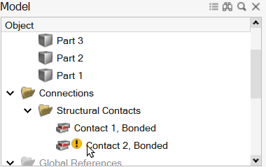
- If a model contains a single contact and disconnected group, you'll be prompted to review them when running analysis.
- A geometric change to a part will mark its contacts, and you'll be
prompted to review them when running analysis.
- If models from previous releases of Inspire are out of synch, you'll be prompted to update contacts.
Defining Group Contacts
Create contacts between groups of parts manually.
-
On the Structure ribbon, select the Contacts tool.

Tip: To find and open a tool, press Ctrl+F. For more information, see Find and Search for Tools. -
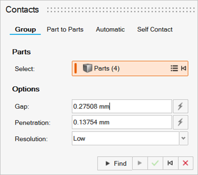
Select the Group tab in the Contacts tool.
-
Select parts in the model.
Note: Click
 to expand or collapse
the list of selected parts. You can right-click a selected part and select
Remove to remove it from the selection.
to expand or collapse
the list of selected parts. You can right-click a selected part and select
Remove to remove it from the selection.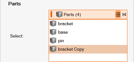
-
Enter the allowed Gap between parts or select
Auto
 to search
automatically.
to search
automatically.
-
Enter the allowed Penetration between parts or select
Auto
to search
automatically.
- Change the Resolution to define the accuracy of the search.
-
Click Find
 to find contacts among
selected parts.
Note: Use the Contact Type for Keep and Find dropdown in to select the type of contacts that are created.
to find contacts among
selected parts.
Note: Use the Contact Type for Keep and Find dropdown in to select the type of contacts that are created. - Right-click and mouse through the check mark to exit, or double-right-click.
Defining Part-to-Part Contacts
Create contacts between parts manually.
-
On the Structure ribbon, select the Contacts tool.
Tip: To find and open a tool, press Ctrl+F. For more information, see Find and Search for Tools. -
Select the Part to Parts tab in the Contacts tool.
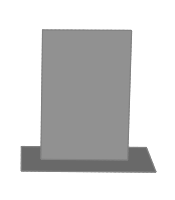
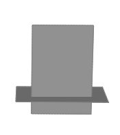
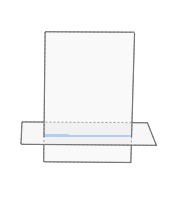
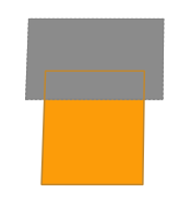
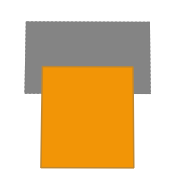
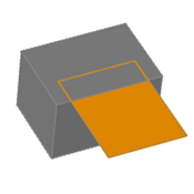
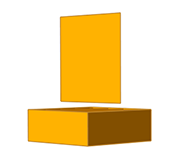
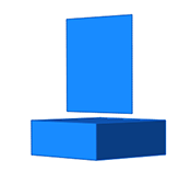
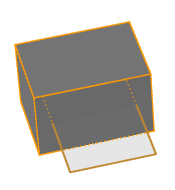
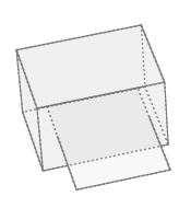
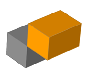
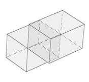
Figure 2. Using OptiStruct 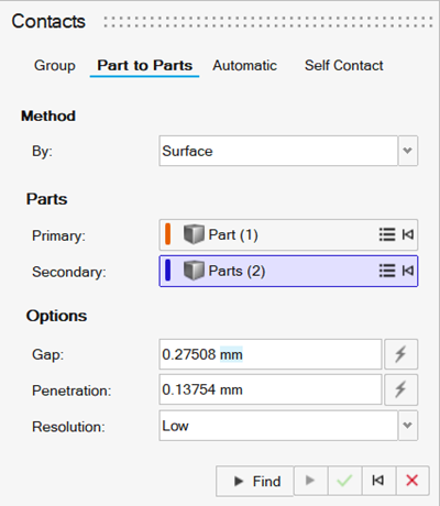
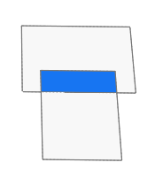
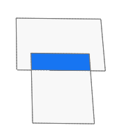
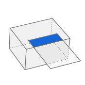
Figure 3. Using SimSolid 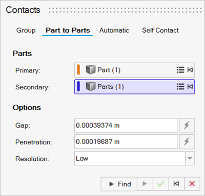
-
Select Surface or Parts from the
By dropdown to choose the detection method.
Note: The Method control is available only when using OptiStruct as the solver.
-
Select the Primary and Secondary
parts in the model.
Note: Click to expand or collapse
the list of selected parts. You can right-click a selected part and select
Remove to remove it from the selection.
-
Enter the allowed Gap between parts or select
Auto
to search
automatically.
-
Enter the allowed Penetration between parts or select
Auto
to search
automatically.
- Change the Resolution to define the accuracy of the search.
-
Click Find
to find contacts among
selected parts.
Note: Use the Contact Type for Keep and Find dropdown in to select the type of contacts that are created.
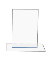
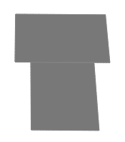
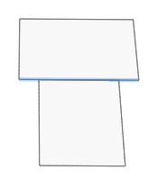
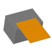
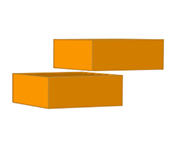
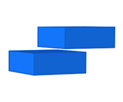
Figure 4. Using OptiStruct 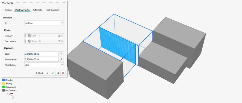
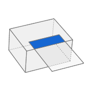
Figure 5. Using SimSolid 
- Right-click and mouse through the check mark to exit, or double-right-click.
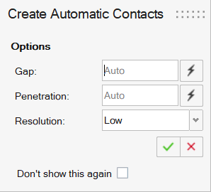
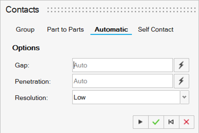
Automatically Defining Contacts
Create contacts between parts automatically.
-
On the Structure ribbon, select the Contacts tool.
Tip: To find and open a tool, press Ctrl+F. For more information, see Find and Search for Tools. -
Select the Automatic tab in the Contacts tool.
-
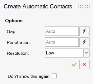
Enter the allowed Gap between parts or select
Auto
to search
automatically.
-
Enter the allowed Penetration between parts or select
Auto
to search
automatically.
-
Change the Resolution to define the accuracy of the
search.
Note: Use the Contact Type for Keep and Find dropdown in to select the type of contacts that are created.
- Right-click and mouse through the check mark to exit, or double-right-click.
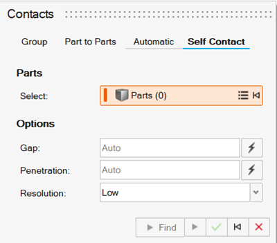
Defining Self Contacts
Create self contact in parts manually.
-
On the Structure ribbon, select the Contacts tool.
Tip: To find and open a tool, press Ctrl+F. For more information, see Find and Search for Tools. -
Select the Self Contact tab in the Contacts tool.
-
Select parts in the model.
Note: Click to expand or collapse
the list of selected parts. You can right-click a selected part and select
Remove to remove it from the selection.
-
Enter the allowed Gap between parts or select
Auto
to search
automatically.
-
Enter the allowed Penetration between parts or select
Auto
to search
automatically.
- Change the Resolution to define the accuracy of the search.
-
Click Find
to find self-contacts
for the selected parts.
Note: Use the Contact Type for Keep and Find dropdown in to select the type of contacts that are created.
- Right-click and mouse through the check mark to exit, or double-right-click.
Reviewing and Editing Contacts
Click a selected contact to open a microdialog and change the type. The options are Bonded, Sliding, Separating, or No Contact.
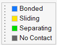
- Select Bonded if parts are bonded or glued together.
- Select Sliding if there is relative sliding between the parts.
- Select Separating if the relative parts can separate.
- Select No Contact if parts are close, but you don't want them to have contact.
- Change the Resolution to define the accuracy of the search.
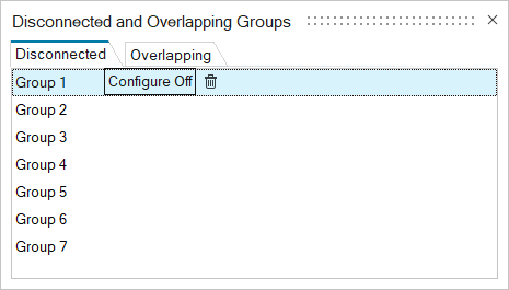
Disconnected and Overlapping Groups
Find and review any disconnected or overlapping groups of parts using the Disconnected Groups tool on the Contacts icon.
| To | Do this | Note |
|---|---|---|
| Configure off a group | In the Disconnected and Overlapping Groups dialog, select the desired group, and then select Configure Off. | When the group is configured off, it's excluded from calculations like mass summaries, static weight calculations, optimization, etc. |
| Delete a group (Del) |
|
|
| Fit a group (F) | Select the group, and then press
F. To show the entire model, press F again. |
The view is adjusted to fit tightly around the selected groups. If no groups are selected, the view fits all shown groups. |
| Isolate a group (I) | Select the group, and then press I.
To show the entire model, press I again. |
Isolating an object zooms in and temporarily hides all other objects. |
 .
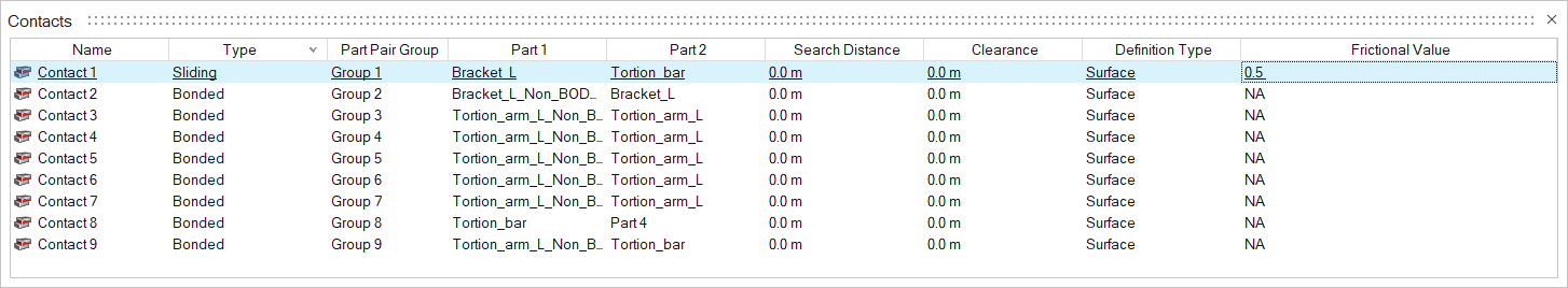
. Contacts Table
The Contacts table lists all of the contacts in your model including the type of connection and the parts it connects.
Click the Open Contacts Table ![]() satellite icon
on the Contacts tool to display the table.
satellite icon
on the Contacts tool to display the table.
The table data can be edited with the following actions:
| To | Do this | Note |
|---|---|---|
| Filter the contacts list | At the top of the table, select Show All Contacts to
show all contacts or select the contact types you want to include in the
display.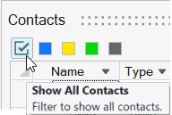 |
|
| Rename a contact | Select the cell in the table and then click again to make the field editable. | |
| Change the connection type | Select the cell in the table and then select a different option from the list. | |
| Change the search distance | Select the cell in the table and then enter a value. | This shows the minimum gap (the exact minimum distance between the two
parts). The search distance for an individual contact defined in this table
will override the global Auto search distance defined in the Find Options |
| Change the clearance |
|
By default, the Contact Clearance and Friction columns are
hidden. Two parts with a 3 mm gap and 1 mm clearance means contact will not occur until the gap decreases to 2 mm. Friction is a range between 0 and 1 where, 0 is sliding and 1 is bonded. |
| Add friction to a Sliding or Separating contact |
|
|
| Sort a column | Click the column header. Click repeatedly to toggle between ascending and descending order. | |
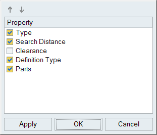
| Add or remove columns | Right-click on a column header. |
 on the guide bar.
- Contact Clearance and Frictional Value columns are hidden by default.
- Two parts with a 3 mm gap and 1 mm clearance will not contact until the gap changes to 2 mm.
- Frictional Value is a range between 0 and 1 where 0 is sliding and 1 is bonded.
Contact Clearance
Contact clearance is an advanced feature used to either force or prevent contact in cases where there is a slight separation between contacting parts. It is only considered when running an analysis or optimization with Sliding or Separating contact types defined.
To edit the contact clearance for an individual contact:
-
Click the List Contacts
 satellite icon on the Contacts tool.
-
Right-click a column header on the Contacts Table and select Clearance to add
it to the table.
- Enter a clearance for the desired contact in the table. To enforce a contact from the beginning of the solution, set the contact clearance to 0.0. If you want the parts to operate independently and only contact if they physically touch during the load case, remove 0.0 and set the value to (none). To enforce an interference fit, enter a positive clearance. To add clearance between touching parts, enter a negative value into the contact clearance field.
Mouse Controls and Keyboard Shortcuts
| To | Do this |
|---|---|
| Select a contact | Left-click a contact to select it. |
| Select multiple contacts | Hold down the Ctrl key and left-click, or use box selection. |
| Deselect contacts | Hold down the Ctrl key and left-click a selected contact. |
| Deselect all contacts | Left-click on an empty space in the modeling window. |
| Delete part contacts | Select a manually defined part contact in the Contacts table and click Delete. |
| Exit the tool | Right-click and mouse through the check mark to exit, or double-right-click. |
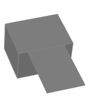
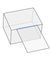
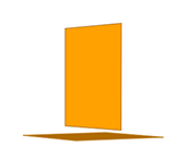
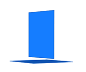
Valid and Invalid Contacts
Inspire detects contact between surfaces and solids, but not all cases are considered valid.
| Geometry | Valid Contact | Description | Type |
|---|---|---|---|
 |
 |
Exact Surface Edge to Surface Face | Surface or Part-to-Part |
 |
 |
Surface Intersection | Surface or Part-to-Part |
 |
 |
Exact Surface Edge to Exact Surface Edge | Surface or Part-to-Part |
 |
 |
Overlapping Surfaces | Surface or Part-to-Part |
 |
 |
Surface to Midsurface | Surface or Part-to-Part |
 |
 |
Overlapping Surface and Solid | Surface or Part-to-Part |
 |
 |
Solid to Midsurface | Surface or Part-to-Part |
 |
 |
Exact Surface Edge to Exact Solid Edge | Surface or Part-to-Part |
 |
 |
Surface to Surface at a Distance | Part-to-Part only |
 |
 |
Surface to Solid at a Distance | Part-to-Part only |
 |
 |
Solid to Solid at a Distance | Part-to-Part only |
| Geometry | Invalid Contact | Description |
|---|---|---|
 |
 |
Surface and Solid Intersection |
 |
 |
Exact Solid Edge to Exact Solid Edge |