Frequency Constraints
In some cases, you may want to change the natural frequency of an object, so as to avoid resonance with other parts in your design. Use frequency constraints to control the frequency at which an optimized part vibrates.
-
On the Structures ribbon, click Run Optimization
 on the
Optimize icon.
on the
Optimize icon. 
Tip: To find and open a tool, press Ctrl+F. For more information, see Find and Search for Tools. - Select the optimization Type.
- Select Maximize Stiffness or Maximize Frequency as the optimization objective.
-
Select an option for Frequency Constraints.
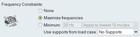
Option Description Maximize Frequencies Select Maximize frequencies. (If you selected Maximize Frequency as the optimization objective, this step is not necessary.) Minimum Select Minimum and enter the lowest frequency you want to allow in the text field. Use the arrows in the scroll menu to select the number of modes that you must exceed the minimum frequency.
- If you want to include supports in the calculation, select the load case that includes the supports you want to use from the Use Supports from Load Case pull-down menu. You can also select No Supports.
- Define additional optimization constraints and options as desired.
- Click Run to start the optimization.
-
When complete, double-click the name of the run to view the results.
Option Description Maximize Frequencies The Shape Explorer displays the frequencies for the first six modes. 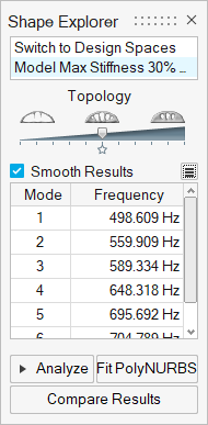
Minimum Frequency Constraint The Shape Explorer displays the frequencies for the modes that you selected. 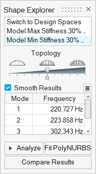 Tip:
Tip:- When maximizing stiffness, you may choose to either maximize frequencies or set a specific minimum frequency. If you choose to maximize frequencies, Inspire will automatically maximize both the stiffness and frequency of the model, and the lowest natural frequency will be displayed in the Shape Explorer window. If the resulting frequency is not high enough to meet your constraint, you may need to assign a stiffer material or modify your mass target for the optimized shape (if running topology optimization).
- When minimizing mass, you may enter a specific minimum frequency and specify how many of the lowest modes must exceed that frequency. If Inspire is unable to achieve the specified frequency for the lowest modes, this will be flagged in the Shape Explorer.
- When maximizing frequency as the optimization objective, you cannot set a minimum frequency, but you can choose whether to include supports from a specific load case.
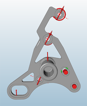
What If I'm Not Achieving My Frequency Constraint?
If your optimized shape is not achieving your desired frequency constraint, you may
need to add material to your part if running a topology optimization. In the example
below, the final part as designed was not achieving the required minimum frequency
of 500 Hz.
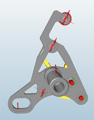
As a result, it was necessary to add three design spaces and apply an extrusion shape
control so that additional material could be added to meet the frequency
constraint.
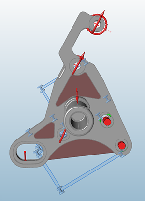
Then an optimization was run, with the objective to minimize mass. Only a frequency
constraint (no stress or displacement constraints) were applied. The image below
shows the resulting shape, with the additional material needed to meet the frequency
constraint displayed in yellow.