Milling
Apply a 5-axis milling constraint when a 5-axis milling machine will be used.
“5-axis” refers to the number of directions in which the cutting tool can move. On a
5-axis machining center, the cutting tool not only moves along the x, y, and z linear
axes, but also rotates about the x- and z-axes. This allows the tool to approach the
workpiece from any direction, allowing complex shapes to be machined. The geometry that
can be machined is constrained by the tool dimensions and subsequent machining access.
The access angle or tool dimensions must also be defined.
Apply a 5-Axis Milling Constraint
Apply a spherical draw direction, used when a machining tool needs a center of a sphere to remove material.
-
On the Structure ribbon, select the Draw Direction tool
on the Shape Controls icon.

Tip: To find and open a tool, press Ctrl+F. For more information, see Find and Search for Tools. -
Select the Milling tool on the secondary ribbon.

-
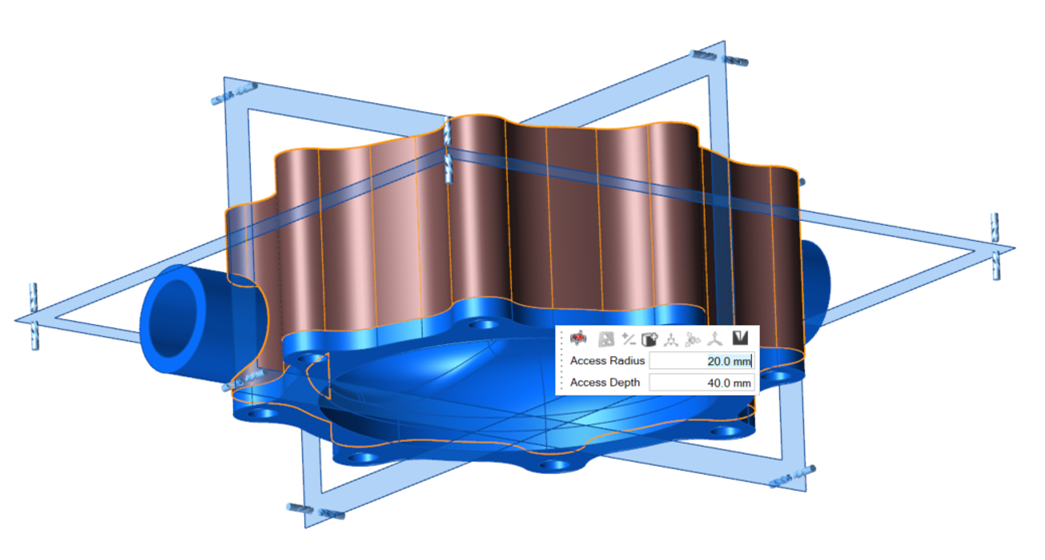
Click a design space to apply a 5-axis milling constraint to one or more parts
of interest.
A microdialog appears, along with a set of three blue orthogonal planes.

-
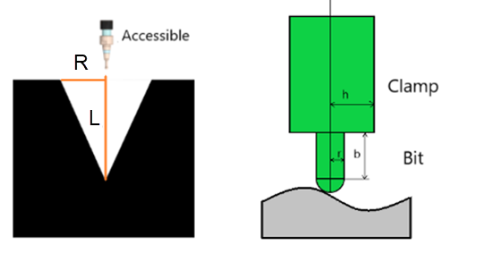
You can define the tooling dimensions by selecting either Access
Angle Parameters or Drill Bill Diameters
from the rightmost dropdown in the microdialog:
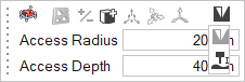
- Access Angle Parameters: Define the access angle
by defining the Access Radius and the
Access Depth, where the angle is r/d.

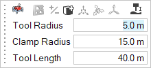
- Drill Bill Diameters: Define the dimensions of
the milling bit and head by entering the Tool
Radius, Tool Length, and
Clamp Radius.
- Access Angle Parameters: Define the access angle
by defining the Access Radius and the
Access Depth, where the angle is r/d.
- Optional:
Click Obstacles
 on the microdialog to designate parts as obstacles
for the machining. These parts will prevent tool access through them.
For more information, see Obstacles.
on the microdialog to designate parts as obstacles
for the machining. These parts will prevent tool access through them.
For more information, see Obstacles. - Right-click and mouse through the check mark to exit, or double-right-click.
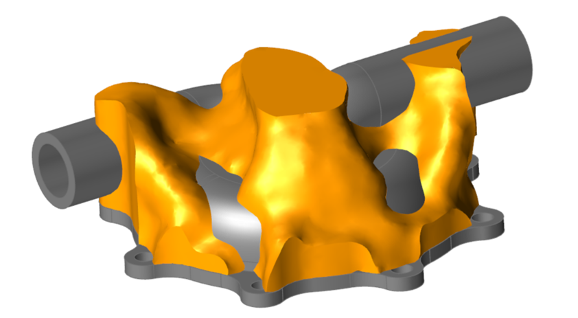
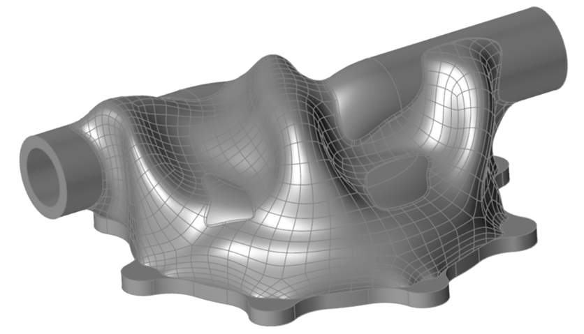
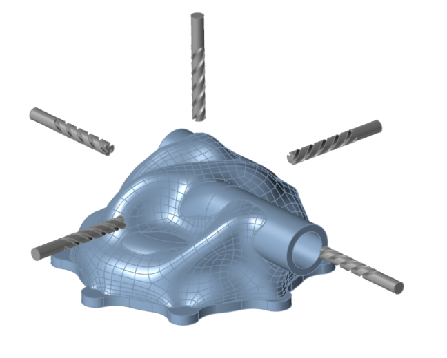
Milling Examples
Pumping Housing Optimization