
g-Loads
g-Loads are used to simulate a model undergoing acceleration, which imparts a force on all of the parts in the model.
Apply g-Loads
-
On the Structure ribbon, select the g-Loads tool.

Tip: To find and open a tool, press Ctrl+F. For more information, see Find and Search for Tools. - Click the point on the model where you want to apply the g-Load.
-
Enter the magnitude of the g-Load in the text field of the microdialog and
press Enter.
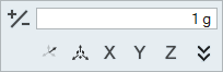
- To reverse the direction of the g-Load, click the +/- button on the microdialog.
- Right-click and mouse through the check mark to exit, or double-right-click.
Tip:
- g-Loads are applied to the entire model rather than a part, and are specific to a load case. If you delete the part where the g-Load is applied, it remains in the model.
- Use the right-click context menu to include or exclude a g-Load from a load case.
Orient g-Loads Using Vectors or Components
You can orient a g-Load by using either vector g-Loads (X, Y, and Z) or component g-Loads (gX, gY, gZ).
-
Select either vector g-Load mode
 or component g-Load mode
  on the
microdialog.
on the
microdialog.
-
Click the chevron
 to expand the microdialog.
- Enter either vector g-Loads (X, Y, and Z) or component g-Loads (gX, gY, gZ).
Microdialog Options
Double-click on a g-Load arrow to enter editing mode, which opens a microdialog.
|
|
Change the direction of the g-Load. |
 |
Enter a magnitude of the g-Load. |
|
|
Click the icon to switch between vector g-Load mode and component g-Load mode. |
|
|
Translate or rotate the g-Load using the Move tool. |
|
|
Align the g-Load to the X, Y, or Z axis. |
|
|
Click the chevron to orient the g-Load by entering either vector g-Loads (X, Y, and Z) or component g-Loads (gX, gY, gZ). |
Mouse Controls and Keyboard Shortcuts
| Right-click and mouse through the check mark to exit, or double-right-click. | Exit the tool. |