Spring Coordinate System
Spring Local Coordinate System
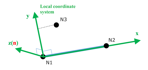
- Local direction: from Node N1 to Node N2
- Local plane: is the plane defined by N1, N2, N3. (N3 optional for 1 DOF springs, if N3 undefined for 3 DOF springs, an appropriate global axis is used).
- Local direction: is normal to the plane starting at N1.
- Local direction: , cross product of the and axis.
The type of spring depends on the property assigned to the spring via the /PART.
Spring Coordinate System for Force Computation
- Property /PROP/TYPE4 (SPRING), /PROP/TYPE32
(SPR_PRE) and /PROP/TYPE35
(STITCH):
These springs all have one degree of freedom and the force is calculated in the local direction of the spring.
- Property /PROP/TYPE8 (SPR_GENE):Force and moment are calculated either from global system or in user specified skew. The spring has six DOF computed.
- If no skew defined then global coordinate system is used
Figure 2. Global coordinate system used in property TYPE8 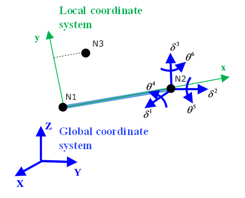
- If skew defined then DOF use skew as,
Figure 3. Skew used in property TYPE8 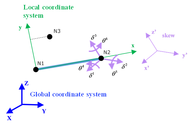
- If no skew defined then global coordinate system is used
- Property /PROP/TYPE13 (SPR_BEAM), /PROP/TYPE25
(SPR_AXI) and /PROP/TYPE44
(SPR_CRUS):These properites may use either original local system or updated local system with skew or global system. Local direction is always from Node N1 to N2. Depending on input, direction may be determined by Node N3, skew or global system. Finally, direction is updated so that it is perpendicular to plane .
- Local direction: From Node N1 to Node N2.
- Local
direction:
- If N3 defined, direction is perpendicular to the plane of N1, N2, N3. These three nodes should not be in a line.
- If N3 not defined but skew defined, then with direction from skew.
- If N3 and skew are not defined, then with Y direction from global system.
-
direction:
direction is computed to be
perpendicular to the plane
,
.
Figure 4. Using skew coordinate system 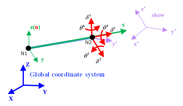
Figure 5. Using global coordinate system 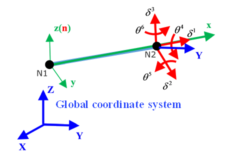
- Property /PROP/TYPE45 (KJOINT2):For each joint type, Node N1 and Node N2 are used to define the joint itself. Node N1 and Node N2 are no longer required to only connect to rigid bodies. Nodes N1, N2 can be non-coincident, but for better behavior of the joints, it is strongly advised to use initially coincident nodes. Optional nodes Node N3, Node N4 are used for the definition of local coordinate systems on two sides of the joint. Initially the coordinate systems are coincident. Behavior of the joint is determined by relative motion/rotation of these local coordinate systems.
Figure 6. 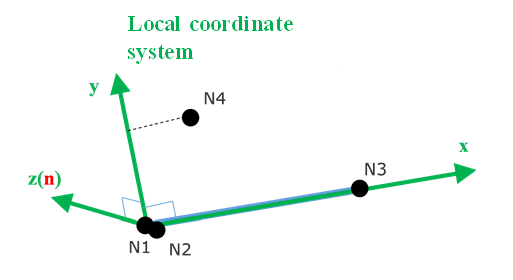
Nodes of the spherical joints N1, N2 should be preferably coincident. Rigid joints may be described by nodes N1, N2. Global coordinate system is used to define initial orientation of the local coordinate system.Type No. Joint Type dx dy dz 1 Spherical √ √ √ 0 0 0 8 Rigid √ √ √ √ √ √ √: denotes a fixed degree of freedom
0: denotes a free (user-defined) degree of freedom
Figure 7. Spherical joint 
For revolute, cylindrical and translational joints, Node N3 is used to define the first axis of the joint local coordinate system. If N3 is not specified, the axis of the joints is defined using the line between node N1 and N2. In this case, nodes N1 and N2 should not be coincident.Type No. Joint Type dx dy dz 2 Revolute √ √ √ 0 √ √ 6 Translational 0 √ √ √ √ √ 3 Cylindrical 0 √ √ 0 √ √ √: denotes a fixed degree of freedom
0: denotes a free (user-defined) degree of freedom
Figure 8. Spherical joint and Translational joint 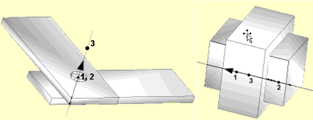
Figure 9. Cylindrical joint and Planar joint 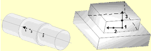
For universal, free, and planar joints, nodes N3 and N4 are used to define the first and the second axes of the joint local coordinate system.Type No. Joint Type dx dy dz 4 Planar √ 0 0 0 √ √ 5 Universal (development source only)
√ √ √ √ 0 0 9 Free 0 0 0 0 0 0 √: denotes a fixed degree of freedom
0: denotes a free (user-defined) degree of freedom
Figure 10. Universal joint 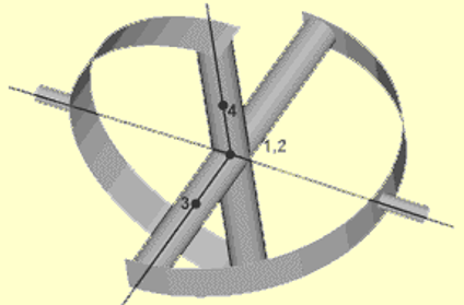
When joint properties are non-isotropic (different stiffness, friction or damping for each non-blocked DOF), a full definition of the local coordinate systems is required. In this case the first axis of the local coordinate system is defined by Node N3, the second axis of the local coordinate system is defined by Node N4, and the third axis is computed automatically.
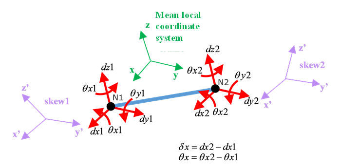
Depending on skew definition, /PROP/TYPE45 (KJOINT2) calculates force and moment.- Take spring local coordinate system.
- Take
- Take mean local coordinate system.
- First set global coordinate system in .
Figure 11. DOF of KJOINT2 properties