
Error Message Database
This section is comprised of error messages in ascending numerical order.
#1 through #299
Error 119
ERROR ID :    119
** ERROR IN INTERFACE DEFINITION
DESCRIPTION :
   -- INTERFACE ID: 3
   -- INTERFACE TITLE: contact
LAGRANGIAN SURFACE IS EMPTYIn 2D analysis (N2D3D=1 or 2 in /ANALY), all mesh must be in YZ plane, and must be in Y positive axis and Z positive axis. If mesh is in Y negative axis or Z negative axis, surface is not found for contact, and this error message will be printed.
In pre-processor (HyperMesh) move all mesh in Y positive axis and Z positive axis.
Error 189
MESSAGE ID :           189
** ERROR : BEGIN IS NOT A VALID KEYWORD
MESSAGE ID :           189
** ERROR : MAT IS NOT A VALID KEYWORDThis message usually occurs when the single file input format is used, and no Engine keywords are defined.
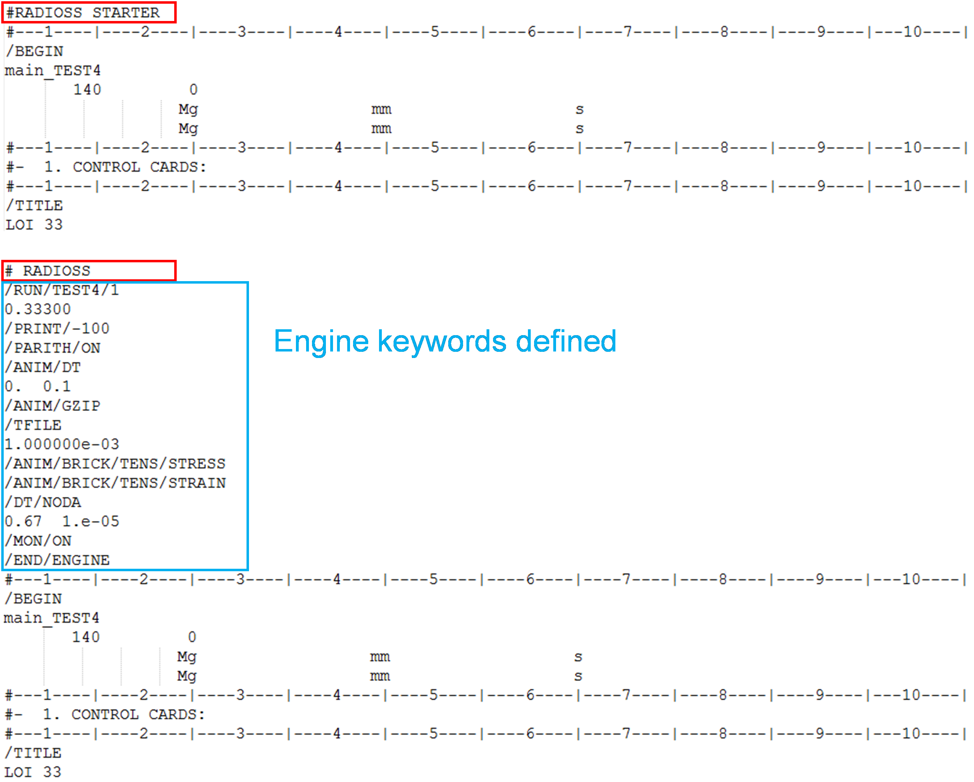
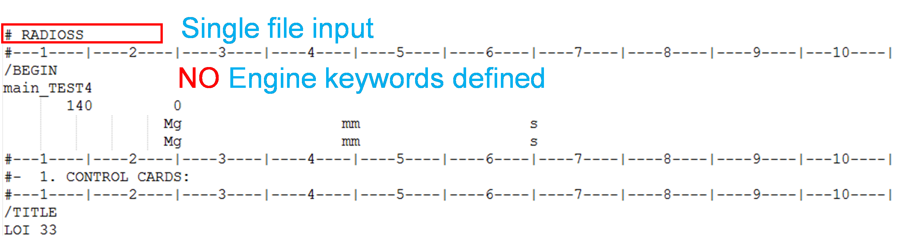
Either use head “#RADIOSS STARTER” or add Engine keywords.
Error 197
ERROR ID :           197
** ERROR IN INPUT DATA
DESCRIPTION :
-- PROPERTY ID : 521003304
   -- PROPERTY TITLE : New PROP 521003304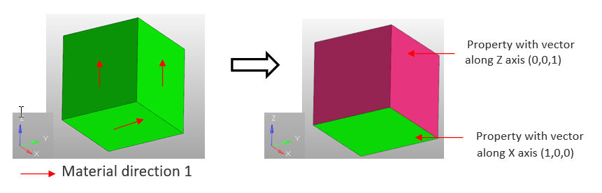
REFERENCE DIRECTION IS ALMOST NORMAL TO SHELL ID=662193988The Starter will print this message when the direction defined in the property (reference vector / skew) is almost normal to a shell element.
The solver provides the property ID (in this example, 521003304) and the shell element ID (in this example, 662193988) for which the reference direction is almost normal to the shell element.
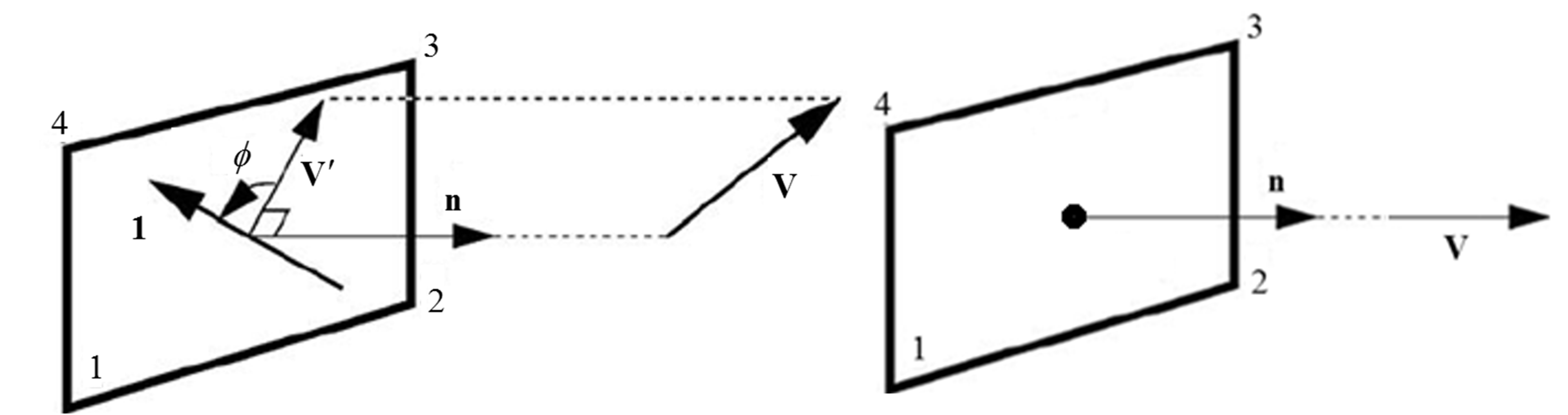
If the material is not really orthotropic (E11=E22 and G12=G23=G31=E11/(2*(1+nu12)), changing the vector will not change the results and an arbitrary vector can be given (VX=VY=VZ=1).
Error 223
ERROR ID: 223
** ERROR IN BEAM DEFINITION

DESCRIPTION :
   IN BEAM ID=1, N1 and N3 HAVE SAME LOCATION

SOLUTION:
   CHANGE N1 OR N3 COORDINATES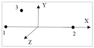
- If the beam cross-section is circular or square (Iyy=Izz), then the same N3 can be assigned to all the beam elements. The main requirement is to pick a node that is valid for all the selected beams: N3 should not lie on the axis of any of the selected beams.
- If Iyy≠Izz, same the node N3 can still be assigned to multiple beam elements if their local X-axis is similar (defined by N1-N2). If the beam local X-axis is not similar, then pick different N3 for different beam: N3 should not lie on the axis of the beam.
#300 through #699
Error 480
ERROR ID :           480
** ERROR IN MATERIAL LAW
DESCRIPTION :
-- MATERIAL ID : 521002880
-- MATERIAL TITLE : Default MAT24 MAT_PIECEWISE_LINEAR_PLASTICITY.2
EPS_T MUST BE STRICTLY LESS THAN EPS_MIn material LAW27 and LAW36, when the failure in tension is defined, there are certain rules that should be followed. In this example the solver is reporting that for material 521002880, which is not allowed.
- LAW36 Example:Eps_t < Eps_m < Eps_f

- LAW27 Example:
EPS_t1 < EPS_m1 < EPS_f1
EPS_t2 < EPS_m2 < EPS_f2
Error 592
ERROR ID :           592
** ERROR IN STARTER INPUT DECK FORMAT
DESCRIPTION :
INPUT VERSION=0
LINE : /VERS/2025
SOLUTION :
/BEGIN CARD IS COMPULSORY FOR STARTER INPUT VERSION >= 50The solver is expecting a /BEGIN card, but instead found a different keyword. Example: /VERS/2025
- The header indicates separate Starter and Engine files, but the Engine file is present underneath the header.
- /BEGIN or /END is missing.
Error 611
MESSAGE ID :           611
** ERROR IN INITIAL PENETRATION IN INTERFACE
DESCRIPTION :           189
-- INTERFACE ID : 11
-- INTERFACE TITLE : Global interface Gap 0.49 Shells Only
INACTI = 6
IMPOSSIBLE TO CHANGE NODE COORDINATES OF SECONDARY NODE : 823868424
** INITIAL PENETRATION = 0.4900000e+00 IMPOSSIBLE TO CALCULATE NEW COORDINATES OF SECONDARY NODE********- Node ID for which a new
position could not be computed (in this example:
823868424) - Interface ID (in this
example:
11)
In HyperMesh, check the initial penetration for the interface ID for which the error occurs.
In most cases, the nodes for which the Starter will not be able to compute a new position will be nodes where the residual distance is equal to 0. This means that the nodes are initially on the main segment.
- Springs that represent
welds or bolts are included in the global contact. They should be
removed.
Figure 6. 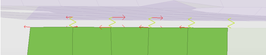
- Mesh issue in an area
where there are some cracks in the mesh. The nodes should be merged/
equivalenced.
Figure 7. 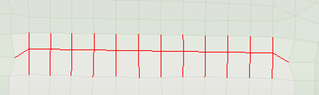
There is a skin on top of the solid mesh and the nodes of the skin/solid are not merged/ equivalenced. The nodes should be merged/ equivalenced.Figure 8. 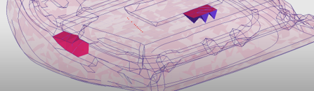
- Solid to solid contact
with 0 gap. This is not supported with interface TYPE7, TYPE11 or
TYPE19. Either move the nodes to create a gap (0.1mm) or use interface
TYPE24 or TYPE25.
Figure 9. 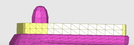
#700 through #1199
Error 953
ERROR ID :           953
** ERROR WHILE READING PARAMETERS
DESCRIPTION :
UNEXPECTED END OF FILE
ERROR ID :           968
** INPUT ERROR
DESCRIPTION :
ERROR WHILE READING STARTER INPUT FILEThis error occurs typically when parameters are present in the input and /END is missing at the end of the file.
In most cases, this occurs when the job was submitted before it finished copying into the scratch directory.
Add /END at the end of the input file or finish copying all input files.
Error 958
ERROR ID :           958
** ERROR DURING PARAMETERS EVALUATION
ERROR ID :           952
** ERROR IN STARTER INPUT DECK FORMAT
DESCRIPTION :
INPUT VERSION=0
LINE : /PARAMETER/GLOBAL/INTEGER/6620015This error occurs when the solver cannot evaluate the value of a parameter. This usually happens when an expression is not complete or there are some parameters referenced in the expression and they are not defined in the model.
Time1” is equal to “ActTTF” +
20. The parameter “ActTTF” is not defined,
so the solver cannot evaluate the value of “Time1”.
Error 1078
ERROR ID :   1078
** ERROR: TIED INTERFACE
DESCRIPTION :
   -- INTERFACE ID: 1
   -- INTERFACE TITLE: new Contact
   1 SECONDARY NODE(S) ARE DEACTIVATED FROM INTERFACE
SECONDARY NODE: 82 NO MAIN SEGMENT FOUND WITHIN 1.0000000000000E-02The solver will print this message when a node is included in an interface TYPE2 and no main segment is found within the search distance for this node and flag “Ignore” is set to 1000.
The solver will provide
the interface ID (in this example 1) and the node ID (in this
example 82) for which the solver did not find a main segment
within the search distance (1.0e-2 in this example).
- Use Ignore = 1, if those nodes do not need to be tied or remove these nodes from the interface TYPE2.
- Translate the nodes that do not find a projection so that they fall within the search distance.
- Increase the search distance slightly (Dsearch).
Error 1104
ERROR ID :           1104
** ERROR WHILE BUILDING SURFACE FROM SOLID PARTS
DESCRIPTION :
-- SURFACE ID : 830005865
-- SURFACE TITLE : New SURF 830005865
UNAVALABLE OPTION /SURF/PART/Surf_ID FOR CREATING SURFACE
SOLUTION :
FOR A PART OF SOLIDS
USE /SURF/PART/EXT/Surf_ID or /SURF/PART/ALL/Surf_IDThe solver will print this message when a PART with solid elements is included in the a /SURF/PART. This keyword allows to build surfaces only from 2D elements and not 3D.
- Run the check named Volumic Parts in Surf in the HyperMesh Model Checker.
- Select either Switch to Surf Ext or Switch to Surf All to automatically switch the keyword to /SURF/PART/EXT or /SURF/PART/ALL.
Error 1130
ERROR ID :           1130
** ERROR IN USER INTERFACE
DESCRIPTION :
OPTION : /MAT/USER1
USER INTERFACE OPTION USED, BUT NO USER INTERFACE ROUTINE IS FOUNDThe Starter will print this message when it reads a user material (LAW29) and the user library defining the behavior and format of this material is not defined.
Replace user material with any other compatible and supported Radioss material keyword.