
/PROP/TYPE9 (SH_ORTH)
Block Format Keyword This property set is used to define the orthotropic shell property.
Format
| (1) | (2) | (3) | (4) | (5) | (6) | (7) | (8) | (9) | (10) |
|---|---|---|---|---|---|---|---|---|---|
| /PROP/TYPE9/prop_ID/unit_ID or /PROP/SH_ORTH/prop_ID/unit_ID | |||||||||
| prop_title | |||||||||
| Ishell | Ismstr | Ish3n | Idrill | P_thickfail | |||||
| hm | hf | hr | dm | dn | |||||
| N | Thick | Ashear | skew_ID | Ithick | Iplas | ||||
| VX | VY | VZ | Ipos | IP | |||||
Definition
| Field | Contents | SI Unit Example |
|---|---|---|
| prop_ID | Property
identifier. (Integer, maximum 10 digits) |
|
| unit_ID | (Optional) Unit identifier. (Integer, maximum 10 digits) |
|
| prop_title | Property
title. (Character, maximum 100 characters) |
|
| Ishell | Shell element formulation
flag. 1
(Integer) |
|
| Ismstr | Shell small strain
formulation flag. 2
(Integer) |
|
| Ish3n | 3 node shell element
formulation flag.
(Integer) |
|
| Idrill | Drilling degree of freedom
stiffness flag. 7
(Integer) |
|
| P_thickfail | Fraction of failed
thickness for shell element deletion. 11
Default = 1.0 (Real) |
|
| hm | Shell membrane hourglass
coefficient. 3 Default = 0.01 Default = 0.1 for hourglass type 3 (Ishell =3) (Real) |
|
| hf | Shell out-of-plane
hourglass. 3 Default = 0.01 Default = 0.1 for hourglass type 3 (Ishell =3) (Real) |
|
| hr | Shell rotation hourglass
coefficient. 3 Default = 0.01 Default = 0.1 for hourglass type 3 (Ishell =3) (Real) |
|
| dm | Shell Membrane Damping It is only active for Material Laws 19, 25, 32 and 36. Default: see Comment 4 (Real) |
|
| dn | Shell numerical damping.
4 It only used for Ishell =12 and 24. Default =0.015 for Ishell =24 (QEPH) Default =0.001 for Ishell =12 (QBAT) Default =0.0001 for Ish3n =30 (DKT18) (Real) |
|
| N | Number of integration
points through the thickness 1 < N <
10. Default set to 1 (Integer) |
|
| Thick | Shell
thickness. (Real) |
|
| Ashear | Shear factor. Default is Reissner value: 5/6 (Real) |
|
| skew_ID | Skew identifier for
reference vector. 8 Default = 0 (Integer) |
|
| Ithick | Shell resultant stresses
calculation flag.
(Integer) |
|
| Iplas | Shell plane stress
plasticity flag for material laws 2, 22, 27, 32, and 36. This flag
is not used for the other material laws. 6 .
(Integer) |
|
| VX | X component. 8 Default = 1.0 (Real) |
|
| VY | Y component. 8 Default = 0.0 (Real) |
|
| VZ | Z component. 8 Default = 0.0 (Real) |
|
| Angle. 8 Default = 0.0 (Real) |
||
| Ipos | Mid shell positioning flag. 12
(Integer) |
|
| IP | Reference direction in
shell plane. 8
(Integer) |
Example (Shell)
#RADIOSS STARTER
#---1----|----2----|----3----|----4----|----5----|----6----|----7----|----8----|----9----|---10----|
#- 1. LOCAL_UNIT_SYSTEm:
#---1----|----2----|----3----|----4----|----5----|----6----|----7----|----8----|----9----|---10----|
/UNIT/2
unit for prop
# MUNIT LUNIT TUNIT
kg mm ms
#---1----|----2----|----3----|----4----|----5----|----6----|----7----|----8----|----9----|---10----|
#- 2. GEOMETRICAL SETS:
#---1----|----2----|----3----|----4----|----5----|----6----|----7----|----8----|----9----|---10----|
/PROP/SH_ORTH/2/2
SH_ORTH example
# Ishell Ismstr Ish3n Idrill Pthick_fail
12 0 0 1 0
# hm hf hr dm dn
0 0 0 .1 .1
# N Thick Ashear skew_ID Ithick Iplas
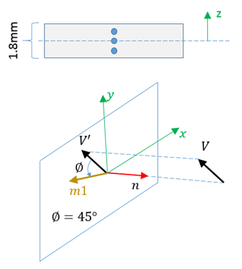
3 1.8 0 0 1 1
# Vx Vy Vz Phi Ipos Ip
1 0 1 45 0 0
#---1----|----2----|----3----|----4----|----5----|----6----|----7----|----8----|----9----|---10----|
#enddata
#---1----|----2----|----3----|----4----|----5----|----6----|----7----|----8----|----9----|---10----|Comments
- Ishell, Ish3n – 4-node and 3-node shell
formulation flag
- Ishell =1,2,3,4 (Q4): original 4 node Radioss shell with hourglass perturbation stabilization.
- Ishell =24 (QEPH): formulation with hourglass physical stabilization for general use.
- Ishell =12 (QBAT): modified BATOZ Q4γ24 shell with four Gauss integration points and reduced integration for in-plane shear. No hourglass control is needed for this shell.
- Ish3n =30 (DKT18): BATOZ DKT18 thin shell with three Hammer integration points.
- Flag Ishell =2 is incompatible with one integration point for shell element.
- Ismstr - Small strain formulation
- Small strain formulation is activated from time t= 0, if Ismstr = 1, 3 or 11. It may be used for a faster preliminary analysis, but the accuracy of results is not ensured. Any shell for which can be switched to a small strain formulation by Radioss Engine option /DT/SHELL/CST, except if Ismstr = 4 or 11.
- If Ismstr =1, 3 or 11, the strains and stresses which are given in material laws are engineering strains and stresses; otherwise, they are true strains and stresses.
- Ismstr =11 has been developed to improve the robustness for Airbag models; actually, it is only compatible with Law 19 and with all quadrilateral shells and standard C0 tria. For Q4 shell using reference state coordinates, when Ismstr = 1, it will be set automatically to Ismstr = 11.
- hm, hf, and hr - Hourglass coefficients
- hm, hf, and hr are only used for Q4 shells (Ishell=1,2,3,4). They must have a value between 0 and 0.05.
- For Ishell=3, default values of hm and hr are 0.1 with larger values possible.
- dm and
dn - Shell membrane damping
and numerical damping coefficient
- Default dm
LAW19 LAW25 LAW32 LAW36 Ishell =1,2,3,4 (Q4) 0.25 0.05 0.0 0.0 Ishell =12 0.25 0.05 0.0 0.0 Ishell =24 0.015 0.015 0.015 0.015 - dn is only used for Ishell =12 and 24 and
Ish3n=30:
- for Ishell = 24, dn is used for hourglass stress calculation
- for Ishell = =12 (QBAT) dn is used for all stress terms, except transverse shear
- for Ish3n=30 (DKT18) dn is only used for membrane
- Default dm
- Ithick - Shell resultant
stresses calculation flag
- Flag Ithick is automatically set to 1 for /MAT/LAW32 (HILL).
- If Ithick=1, the small strain option is automatically deactivated in the corresponding type of element.
- Iplas - Shell plane stress
plasticity flag
- It is recommended to use Iplas = -1, if Ithick = -1.
- If Iplas =1, the small strain option is automatically deactivated in the corresponding type of element.
- Idrill - Drilling degree of freedom stiffness flag
- Drilling DOF stiffness is recommended for implicit solutions especially for Riks method and bending dominated problems.
- Idrill is available for QEPH, QBAT (Ishell = 12 and 24), and standard triangle (C0) shell elements (Ish3n = 1 and 2).
- The orthotropy angle is
defined as following from the reference vector defined in the stack:Where,
- is defined per ply in stack
- is defined on the element
- is defined on the ply
- is defined in the drape table
The reference vector defined with Ip, skew_ID or vector (VX, VY, VZ), is described in Composite Properties in the User Guide.
Figure 2. 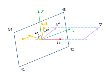 Example for IP = 20:
Figure 3. 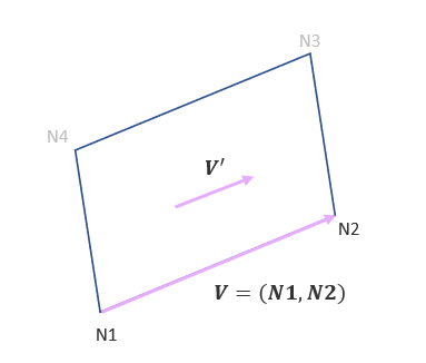
- If IP = 24 and skew_ID = 0, the 1st
material direction (m1) is defined with the node N1 and N2 of the
shell elements of the shell seatbelt (only with
/MAT/LAW119).
Figure 4. 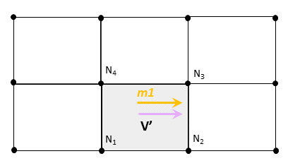
- If IP = 24 and skew_ID ≠ 0, the first direction of
the local coordinate system is used to define the transversal
direction of the shell seatbelt (only with
/MAT/LAW119), the 2nd material
direction m2. The skew (/SKEW/MOV or
/SKEW/MOV2 only) must be defined with two
nodes of the same seatbelt shell element. The third node can be
chosen arbitrarily. The given orientation is propagated to all
connected seatbelt elements.
Figure 5. 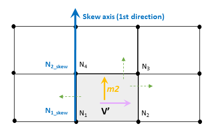
- The material direction
definition in the initial state card (/INISHE/ORTHO,
/INISH3/ORTHO) overwrites the material.
In the case of reference metrics, the orientation for directions of anisotropy must be defined with the reference geometry, not the initial one.
The 2nd material direction m2 is derived from direction m1 rotated 90 degrees (orthotropic).
- The P_thickfail parameter is not compatible with failure defined within the material law itself, such as plastic failure strain in LAW36.
- Element deletion rules
used with P_thickfail and
failure models:
- P_thickfail defined in
both the property and in the failure model(s) (/FAIL)
are considered to trigger the element failure.
- P_thickfail > 0 defines a fraction of failed thickness. This uses the amount of thickness assigned to each integration point.
- P_thickfail < 0 defines a ratio of failed integration points. This uses the number of integration point.
- Minimum of the absolute value defined in the shell property or in the failure criterion card is used to trigger the element failure.
- For fully-integrated shells (Ishell=12), the rules described above for under-integrated shells applies to each Gauss point separately. P_thickfail criterion is checked for all integration point thickness for each in-plane Gauss point. The element is deleted only when all Gauss points reach P_thickfail criterion.
- P_thickfail defined in the property and in the failure model(s) (/FAIL) must use the same sign. Otherwise, the P_thickfail defined in the property takes the same sign as the value defined in the failure criterion card /FAIL.
- P_thickfail rules are not used with failure models defined inside the material laws. It is used only for the failure model defined with /FAIL.
- P_thickfail defined in
both the property and in the failure model(s) (/FAIL)
are considered to trigger the element failure.
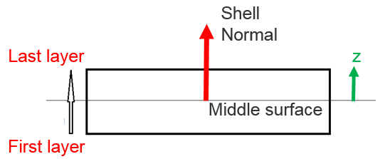
- Ipos: Shell position or thickness offset:
- Ipos=0: No shell offset
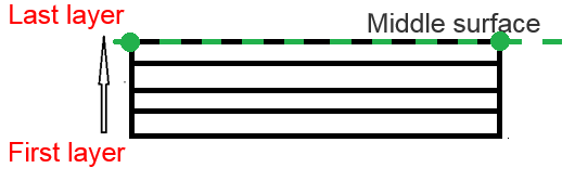
- Ipos=3: The upper surface is coincident with the
element mid-surface.
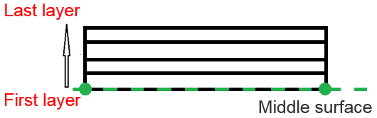
- Ipos=4: The lower surface is coincident with the
element mid-surface.
- Ipos=0: No shell offset