
/PROP/TYPE16 (SH_FABR)
Block Format Keyword This property is used to define the anisotropic layered shell property. This property is currently only compatible with elastic anisotropic fabric (/MAT/LAW58 (FABR_A)).
Format
| (1) | (2) | (3) | (4) | (5) | (6) | (7) | (8) | (9) | (10) |
|---|---|---|---|---|---|---|---|---|---|
| /PROP/TYPE16/prop_ID/unit_ID or /PROP/SH_FABR/prop_ID/unit_ID | |||||||||
| prop_title | |||||||||
| Ishell | Ismstr | Ish3n | P_thickfail | ||||||
| hm | hf | hr | dm | dn | |||||
| N | Thick | Ashear | Ithick | ||||||
| VX | VY | VZ | skew_ID | Ipos | IP | ||||
| (1) | (2) | (3) | (4) | (5) | (6) | (7) | (8) | (9) | (10) |
|---|---|---|---|---|---|---|---|---|---|
| ti | Zi | mat_IDi | |||||||
Definition
| Field | Contents | SI Unit Example |
|---|---|---|
| prop_ID | Property
identifier. (Integer, maximum 10 digits) |
|
| unit_ID | Unit identifier. (Integer, maximum 10 digits) |
|
| prop_title | Property
title. (Character, maximum 100 characters) |
|
| Ishell | Shell element formulation flag.
(Integer) |
|
| Ismstr | Shell small strain
formulation flag.
(Integer) |
|
| Ish3n | 3 node shell element
formulation flag.
(Integer) |
|
| P_thickfail | Fraction of failed
thickness for shell element deletion. 8
Default = 1.0 (Real) |
|
| hm | Shell membrane hourglass
coefficient. Only used when Ishell =1, 2, 3, 4 Default = 0.01 Default = 0.1 for Ishell =3 (Real) |
|
| hf | Shell out-of-plane
hourglass. Only used when Ishell =1, 2, 3, 4 Default = 0.01 (Real) |
|
| hr | Shell rotation hourglass
coefficient. Only used when Ishell =1, 2, 3, 4 Default = 0.01 Default = 0.1 for Ishell =3 (Real) |
|
| dm | Shell membrane
damping. Used only for material LAW58. Default =0.075 for Ishell =1, 2, 3, 4 Default= 0.15 for Ishell =24 Default =0.2 for Ishell =12 Default = 0.0 for all 3 node shells (Real) |
|
| dn | Shell numerical damping.
10 Only used for Ishell =12, 24 and Ish3n = 30 Default =0.015 for Ishell =24 (QEPH) Default =0.001 for Ishell =12 (QBAT) Default =0.0001 for Ish3n =30 (DKT18) (Real) |
|
| N | Number of layers, with
. 7
Default = 1 (Integer) |
|
| Thick | Shell
thickness. (Real) |
|
| Ashear | Shear factor. Default is Reissner value: 5/6 (Real) |
|
| Ithick | Shell resultant stresses
calculation flag.
(Integer) |
|
| VX | X component for reference
vector. 3 Default = 1.0 (Real) |
|
| VY | Y component for reference
vector. Default = 0.0 (Real) |
|
| VZ | Z component for reference
vector. Default = 0.0 (Real) |
|
| skew_ID | Skew identifier for
reference vector. 3 Default = 0 (Integer) |
|
| Ipos | Layer positioning flag for
reference vector. 5
Default = 0 (Integer) |
|
| IP | Reference direction in
shell plane. 3
(Integer) |
|
| Angle
of 1st local axis for layer
i. 3 (Real) |
||
| Angle between first and
second axis. 3 Default = 90.0 (Real) |
||
| ti | Thickness
ti of layer
i. (Real) |
|
| Zi | Z position of layer i
(Zi defines the
position of the middle of the layer). Default = 0.0 (Real) |
|
| mat_IDi | Material identifier for
layer i. Same material should be used for all
layers. (Integer) |
Example
#RADIOSS STARTER
#---1----|----2----|----3----|----4----|----5----|----6----|----7----|----8----|----9----|---10----|
#-  1. LOCAL_UNIT_SYSTEm:
#---1----|----2----|----3----|----4----|----5----|----6----|----7----|----8----|----9----|---10----|
/UNIT/2
unit for PROP
#              MUNIT               LUNIT               TUNIT
                  Mg                  mm                   s
#---1----|----2----|----3----|----4----|----5----|----6----|----7----|----8----|----9----|---10----|
#-  2. GEOMETRICAL SETS:
#---1----|----2----|----3----|----4----|----5----|----6----|----7----|----8----|----9----|---10----|
/PROP/TYPE16/2/2
prop type 16
#   Ishell    Ismstr     Ish3n                                       Pthick_fail
         0         0         0                                                 0
#                 hm                  hf                  hr                  dm
                   0                   0                   0                   0
#        N                         Thick              Ashear              Ithick
         3                           1.6                   0                   0
#                 Vx                  Vy                  Vz   skew_ID      Ipos                  Ip
                   1                   0                   1         0         0                   0
#                Phi               Alpha                  Ti                  Zi   mat_IDi
                  45                  90                  .5                             1
                  90                  90                  .6                             2
                 -45                  90                  .5                             1
#---1----|----2----|----3----|----4----|----5----|----6----|----7----|----8----|----9----|---10----|
#enddata
#---1----|----2----|----3----|----4----|----5----|----6----|----7----|----8----|----9----|---10----|
Comments
- Ishell – 4-node shell
formulation flag
The hourglass formulation is visco-elastic for Q4 shells (Ishell=1,2,3,4).
- hm, hf, and hr - Hourglass coefficients
- hm, hf, and hr are used only for Q4 shells (Ishell=1,2,3,4). They must have a value between 0 and 0.05.
- For Ishell=3, default values of hm and hr are 0.1 with larger values possible.
- The orthotropy angle
is defined as following from the reference vector defined in the stack.Where,
- is defined per ply in stack
- is defined on the element
- is defined on the ply
- is defined in the drape table
The reference vector , defined with IP, skew_ID, or vector VX, VY and VZ, is described in Composite Properties in the User Guide.Figure 1. 
- Example for IP = 20
Figure 2. 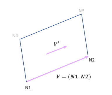
- The material direction definition in the initial state card
(/INISHE/ORTHO, /INISH3/ORTHO)
overwrites the material direction.
In case of reference metrics, the orientation for directions of anisotropy must be defined with the reference geometry, not the initial one.
The 2nd material direction m2 is derived from direction m1 with the angle .
If , the layer is orthotropic.
- Ipos – Layer position
Ipos= 0: layer positions are calculated automatically.
If ,- A warning message is displayed
- Individual layer thickness will be adjusted to new layer thickness
with:Here "Thick" and are the shell thickness and layer thickness which are specified in input.
Figure 3. 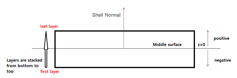
- Ipos = 1: all
layer positions in the element thickness are user-defined (with
and
).
- “Thick” is not checked, as it does not need to be equal to the sum of layer thickness.
- Multiple layers are allowed to have the same space position.
For more details, refer to Layer thickness and position calculation. in FAQs.
- The material law number given in /PART will be used to define the density and Young’s modulus which then is used to calculate the time step and interface stiffness.
- Each i layer has only 1 integration point through its thickness.
- Element deletion rules
used with P_thickfail and
failure models:
- Only P_thickfail
defined in the property is considered to trigger the element failure.
- P_thickfail > 0 defines a fraction of failed thickness. This uses the amount of element global thickness assigned to each layer.
- P_thickfail < 0 defines a ratio of failed layers. This uses the number of layers.
- The P_thickfail defined in failure model(s) (/FAIL) are not used.
- For fully-integrated shells (Ishell=12), the rules described above for under-integrated shells applies to each Gauss point separately. P_thickfail criterion is checked for all layers thickness for each in-plane Gauss point. The element is deleted only when all Gauss points reach P_thickfail criterion.
- P_thickfail rules are not used with failure models defined inside the material laws. It is used only for the failure model defined with /FAIL.
- Only P_thickfail
defined in the property is considered to trigger the element failure.
- Thickness is constant for material /MAT/LAW58. Flag Ithick is not used for this material.
- Shell numerical
damping coefficient dn is only
used for Ishell=12, 24 and Ish3n=30:
- Ishell =24 (QEPH) dn is used for hourglass stress calculation.
- Ishell =12 (QBAT) dn is used for all stress terms.
- Ish3n =30 (DKT18) dn is used for all stress terms, except transverse shear.