/INTER/TYPE20 (Obsolete)
Block Format Keyword This is a general single surface or surface to surface contact interface.
Edge to edge contact is also possible. Penalty stiffness is constant and therefore the time step is not affected (for standard penalty stiffness). This contact interface can replace interface TYPE3, TYPE5, TYPE7, TYPE11 or TYPE19. The interface is basically defined in terms of one or two surfaces. If only one surface is used, this surface is self-impacting. If two surfaces are defined, nodes of surface two impact surface one. A symmetric treatment can be activated. Edges of surface one and two can be taken into account for the contact. Nodes can be added to surface.
Format
| (1) | (2) | (3) | (4) | (5) | (6) | (7) | (8) | (9) | (10) |
|---|---|---|---|---|---|---|---|---|---|
| /INTER/TYPE20/inter_ID/unit_ID | |||||||||
| inter_title | |||||||||
| surf_ID1 | surf_ID2 | Isym | Iedge | grnd_ID | line_ID1 | line_ID2 | edge_angle | ||
| Igap | Ibag | Idel | |||||||
| Fpenmax | |||||||||
| Blank Format | |||||||||
| (1) | (2) | (3) | (4) | (5) | (6) | (7) | (8) | (9) | (10) |
|---|---|---|---|---|---|---|---|---|---|
| Stfac | Fric | Gap0 | Tstart | Tstop | |||||
| IBC | Inacti | VISs | VISF | ||||||
| Ifric | Ifiltr | Xfreq | Iform | ||||||
| (1) | (2) | (3) | (4) | (5) | (6) | (7) | (8) | (9) | (10) |
|---|---|---|---|---|---|---|---|---|---|
| C1 | C2 | C3 | C4 | C5 | |||||
| (1) | (2) | (3) | (4) | (5) | (6) | (7) | (8) | (9) | (10) |
|---|---|---|---|---|---|---|---|---|---|
| C6 | |||||||||
Definition
| Field | Contents | SI Unit Example |
|---|---|---|
| inter_ID | Interface
identifier (Integer, maximum 10 digits) |
|
| unit_ID | Unit Identifier (Integer, maximum 10 digits) |
|
| inter_title | Interface
title (Character, maximum 100 characters) |
|
| surf_ID1 | First surface
identifier (Integer) |
|
| surf_ID2 | Second surface identifier
(Integer) |
|
| Isym | Symmetric contact
treatment of the nodes and the surface flag
(Integer) |
|
| Iedge | Edge definition flag
(Integer) |
|
| grnd_ID | Nodes group identifier used to add nodes to surface
nodes (Integer) |
|
| line_ID1 | First line identifier (Integer) |
|
| line_ID2 | Second line
identifier (Integer) |
|
| edge_angle | Edges angle Default = 91 (Real) Use only if Iedge = 3 If angle between two edges is smaller than edge_angle, the edge is considered. |
|
| Igap | Gap/element option flag.
(Integer) |
|
| Ibag | Airbag vent holes closure
flag in case of contact.
(Integer) |
|
| Idel | Node and segment deletion
flag. 5
(Integer) |
|
| Fpenmax | maximum initial
penetration factor (0 < Fpenmax ≤ 1). 10 Default = 1.0 (Real) |
|
| Stfac | Interface stiffness scale
factor. Default = 1 (Real) |
|
| Fric | Coulomb
friction. (Real) |
|
| Gap0 | Minimum gap for impact
activation. 6
If Igap = 0 default is:
(Real) |
|
| Tstart | Start
time. (Real) |
|
| Tstart | Time for temporary
deactivation. (Real) |
|
| IBC | Deactivation flag of
boundary conditions at impact. (Boolean) |
|
| Inacti | Deactivation flag of
stiffness in case of initial penetrations. 9
(Integer) |
|
| VISs | Critical damping
coefficient on interface stiffness. Default = 0.05 (Real) |
|
| VISF | Critical damping
coefficient on interface friction. Default = 1.0 (Real) |
|
| Ifric | Friction formulation flag.
13
14
(Integer) |
|
| Ifiltr | Friction filtering flag.
15
(Integer) |
|
| Xfreq | Filtering
coefficient. (Real) |
|
| Iform | Friction penalty
formulation type.
(Integer) |
|
| C1 | Friction law
coefficient. (Real) |
|
| C2 | Friction law
coefficient. (Real) |
|
| C3 | Friction law
coefficient. (Real) |
|
| C4 | Friction law
coefficient. (Real) |
|
| C5 | Friction law
coefficient. (Real) |
|
| C6 | Friction law
coefficient. (Real) |
Flags for Deactivation of Boundary Conditions: IBC
| (1)-1 | (1)-2 | (1)-3 | (1)-4 | (1)-5 | (1)-6 | (1)-7 | (1)-8 |
|---|---|---|---|---|---|---|---|
| IBCX | IBCY | IBCZ |
Definition
| Field | Contents | SI Unit Example |
|---|---|---|
| IBCX | Deactivation flag of X
boundary condition at impact.
(Boolean) |
|
| IBCY | Deactivation flag of Y
boundary condition at impact.
(Boolean) |
|
| IBCZ | Deactivation flag of Z
boundary condition at impact.
(Boolean) |
Comments
- The simplest input is to enter only one self-impacting surface surf_ID1. Symmetric treatment flag Isym is used for node to surface contact but edge to edge contact is always symmetric.
- To emulate an interface TYPE7 or
TYPE11 input:
TYPE20 to Emulate TYPE7 Input TYPE20 to Emulate TYPE11 Input (TYPE20) surf_ID1 = surf_IDm (TYPE7) (TYPE20) grnd_ID = grnd_IDs (TYPE7)
(TYPE20) line_ID1 = line_IDs (TYPE11) (TYPE20) line_ID2 = line_IDm (TYPE11)
(TYPE20) line_ID1 = 0
(TYPE20) line_ID2 = 0
(TYPE20) surf_ID1 = 0 (TYPE20) grnd_ID = 0
(TYPE20) surf_ID2 = 0 (TYPE20) Isym = 2
(TYPE20) Iedge = 0
(TYPE20) surf_ID2 = 0 (TYPE20) Isym = 0
(TYPE20) Iedge = 0
- In case of SPMD, each main segment defined by surf_IDm must be associated to an element (possibly to a void element).
- For the flag Ibag, refer to the monitored volume option (Monitored Volumes (Airbags)).
- Flag Idel = 1 has a CPU cost higher than Idel = 2.
- If Igap = 0, a default
value used for Gap0, which is
computed as:
(1) With,- t
- Average thickness of the main shell elements
- l
- Average side length of the main brick elements
- lmin
- Smallest side length of all main segments (shell or brick)
- If Igap = 1, the gap is
computed for each impact as:
(2) With,- gm: main element gap:
, with t is the thickness of the main element for shell elements
gm = 0 for brick elements
- gs: secondary node
gap:
gs = 0 if the secondary node is not connected to any element or is only connected to brick or spring elements.
, with t is the largest thickness of the shell elements connected to the secondary node.
for truss and beam elements, with S being the cross section of the element.
If the secondary node is connected to multiple shells and/or beams or trusses, the largest computed secondary gap is used.
If the free edge of a shell element is in contact, then Igap can shift the gap of the free edges border shells, as:
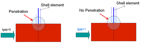
Figure 1.
- gm: main element gap:
- Deactivation of the boundary condition is applied to secondary nodes group (surf_IDs).
- Inacti = 3 may create
initial energy if the node belongs to a spring element.Inacti = 5:

Figure 2. - Maximum penetration value is set
as a fraction of the actual gap (including variable gap):
If the initial penetration of a secondary node is greater than the calculated maximum value (Fpenmax), the node will be deactivated from the interface (node stiffness deactivation).
- One node can belong to the two surfaces at the same time.
- There is no limitation value to the stiffness factor (but a value can be greater than 1.0 can reduce the initial time step).
- For Friction Formulation:
- If the friction flag is 0 (default), the old static
friction formulation is used:
with ( is Coulomb friction coefficient)
- For flag Ifric > 0, new
friction models are introduced. In this case, the friction coefficient is
set by a function
,Where,
- Pressure of the normal force on the main segment
- Tangential velocity of the secondary node
- If the friction flag is 0 (default), the old static
friction formulation is used:
- Currently, the coefficients C1 through C6 are used to define a variable
friction coefficient
for new friction formulations.The following formulations are available:
- Ifric = 1
(Generalized viscous friction law):
(3) - Ifric = 2
(Modified Darmstad law):
(4) - Ifric = 3
(Renard law):
if
if
if
Where,
- First critical velocity must be different to 0 ( ).
- First critical velocity must be lower than the second critical velocity ( ).
- The static friction coefficient and the dynamic friction coefficient , must be lower than the maximum friction ( and ).
- The minimum friction coefficient , must be lower than the static friction coefficient and the dynamic friction coefficient ( and )
- Ifric = 1
(Generalized viscous friction law):
- Friction filtering:If Ifiltr ≠ 0, the tangential forces are smoothed using a filter:
(5) Where, coefficient is calculated from:- If Ifiltr= 1 , simple numerical filter
- If Ifiltr = 2 , standard -3dB filter, with , and T is filtering period
- If Ifiltr = 3
, standard -3dB filter, with Xfreq is cutting frequency
The filtering coefficient Xfreq should have a value between 0 and 1.
- Friction penalty formulation Iform
- If Iform = 1,
(default) viscous formulation, the friction forces are:
(6) While an adhesion force is computed as:
with
- If Iform = 2,
stiffness formulation, the friction forces are:
(7) While an adhesion force is computed as:
with
Where, Vt is contact tangential velocity.
- If Iform = 1,
(default) viscous formulation, the friction forces are: