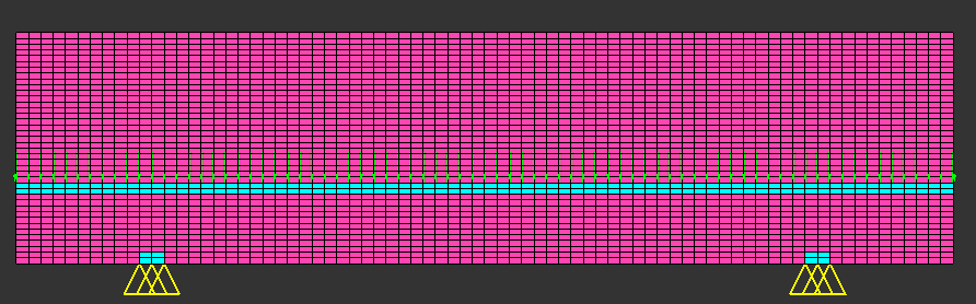
The suspension bridge topology is an optimal structure generated under a distributed
load. A fine mesh is generated to simulate the design space and loads are applied. The
distributed load forms a single load case.
Model Files
Before you begin, copy the file(s) used in this example to
your working directory.
The objective function (compliance) is a subcase dependent response, therefore the
response reference is part of the subcase definition. The constraint (volume
fraction) is a global response, therefore the reference is outside of the
subcase.
The responses and constraints are defined in the Bulk Data section. Two responses are
defined here: the compliance, which is referenced by the objective function, and the
volume fraction, which is referenced by the constraint statement to put up an upper
bound of 0.2 (20% of the design space volume). The constraint statement is then
referenced as a global constraint in the subcase
section.
BEGIN BULK
$
DRESP1,1,comp,COMP
DRESP1,2,volfrac,VOLFRAC
DCONSTR,2,2,,0.2
Figure 1. Loads and Constraints for Suspension Bridge
This example is analyzed in the one-file setup with the file,
bridge.fem. The OptiStruct
batch job is submitted using the command shell script, % optistruct
bridge.
Results
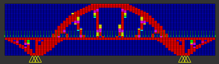
The optimization converges in 24 iterations. The solution is well defined with
discrete truss members connecting the load carrying arch to the load applied points.
The results are requested in HyperMesh binary format and
written to the file, bridge.res. The shape of the solution at
the final iteration is visualized by creating a contour plot of the density results
at the 24th iteration in the HyperMeshContour panel.Figure 2. Design Topology for Suspension Bridge with All Loads Weighted
Equally