OptiStruct is a proven, modern structural solver with comprehensive, accurate and scalable solutions for linear and nonlinear
analyses across statics and dynamics, vibrations, acoustics, fatigue, heat transfer, and multiphysics disciplines.
The OptiStruct Example Guide is a collection of solved examples for various solution sequences and optimization types and provides
you with examples of the real-world applications and capabilities of OptiStruct.
This section presents nonlinear small displacement analysis examples generated using OptiStruct. Each example uses a problem description, execution procedures, and results to demonstrate how OptiStruct is used.
This section presents nonlinear large displacement analysis examples generated using OptiStruct. Each example uses a problem description, execution procedures, and results to demonstrate how OptiStruct is used.
This section presents nonlinear transient analysis examples generated using OptiStruct. Each example uses a problem description, execution procedures, and results to demonstrate how OptiStruct is used.
This section presents normal modes analysis examples generated using OptiStruct. Each example uses a problem description, execution procedures, and results to demonstrate how OptiStruct is used.
This section presents complex eigenvalue analysis examples generated using OptiStruct. Each example uses a problem description, execution procedures, and results to demonstrate how OptiStruct is used.
This section presents thermal and heat transfer analysis examples generated using OptiStruct. Each example uses a problem description, execution procedures, and results to demonstrate how OptiStruct is used.
This section presents analysis technique examples generated using OptiStruct. Each example uses a problem description, execution procedures, and results to demonstrate how OptiStruct is used.
The suspension bridge topology is an optimal structure generated under a distributed load. A fine mesh is generated
to simulate the design space and loads are applied. The distributed load forms a single load case.
The air conditioner bracket is an optimal topology structure generated under both linear static stiffness and modal frequency
response. Shell elements are used to ensure that the bracket is manufacturable using a casting process.
Multi-Model Optimization can be used in applications that require optimizing parts of different sizes. This is accomplished
by using the SCALE continuation line on linked DTPL and DSIZE entries in the models on which the scaled design is to be applied.
Multi-Model Optimization is demonstrated in this Excavator example using Topology optimization design variables that are
linked between the two models.
Demonstrates topology optimization of a V-bracket with RADOPT technique, using OptiStruct. RADOPT is Radioss optimization using OptiStruct. The equivalent static load method (ESLM) is used to perform the optimization run here.
Topology optimization of a cylinder block with a bore will be performed. The cylinder block is modeled using first
order solid (Hexa and Penta) elements.
Multi-Material Optimization (MMO) can be used in applications that require optimizing the parts of different materials.
This method offers an initial concept-level look at material placement within the structure, where multiple materials
can be evaluated.
Multi-Material Optimization (MMO) can be used in applications that require optimizing the parts of different materials.
This method offers an initial concept-level look at material placement within the structure, where multiple materials
can be evaluated.
This section presents shape optimization example problems, solved using OptiStruct. Each example uses a problem description, execution procedures and results to demonstrate how OptiStruct is used in shape optimization.
The examples in this section demonstrate how topography optimization generates both bead reinforcements in stamped
plate structures and rib reinforcements for solid structures.
The examples in this section demonstrate how the Equivalent Static Load Method (ESLM) can be used for the optimization
of flexible bodies in multibody systems.
This section presents multiphysic examples generated using OptiStruct. Each example uses a problem description, execution procedures, and results to demonstrate how OptiStruct is used.
This section presents response spectrum examples generated using OptiStruct. Each example uses a problem description, execution procedures, and results to demonstrate how OptiStruct is used.
This section presents nonlinear explicit analysis examples generated using OptiStruct. Each example uses a problem description, execution procedures, and results to demonstrate how OptiStruct is used.
This section presents piezoelectric analysis examples generated using OptiStruct. Each example uses a problem description, execution procedures, and results to demonstrate how OptiStruct is used.
The OptiStruct Example Guide is a collection of solved examples for various solution sequences and optimization types and provides
you with examples of the real-world applications and capabilities of OptiStruct.
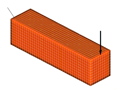
The design space consists of a cantilever beam loaded at the mid-section of the free
end.
Subcase Section
The objective
function (compliance) is a subcase dependent response, therefore the response
reference is part of the subcase definition. The constraint (volume fraction) is
a global response, therefore the reference is outside the
subcase.
The responses and
constraints are defined in the Bulk Data section. Two responses are defined
here: the compliance, which is referenced by the objective function, and the
volume fraction, which is referenced by the constraint statement to put up an
upper bound of 0.25 (25% of the design space volume). The constraint statement
is then referenced as a global constraint in the subcase
section.
BEGIN BULK
$
DRESP1,1,comp,COMP
DRESP1,2,volfrac,VOLFRAC
DCONSTR,2,2,,0.2
The volume fraction constraint is set to 25%
of the total design material. In the beam.fem file, the
following PSOLID entry is used:
(1)
(2)
(3)
(4)
(5)
(6)
(7)
(8)
(9)
PSOLID
1
1
1
The "1" in the 9th field denotes that the component is designated
as design material. The example is run for 20 iterations.
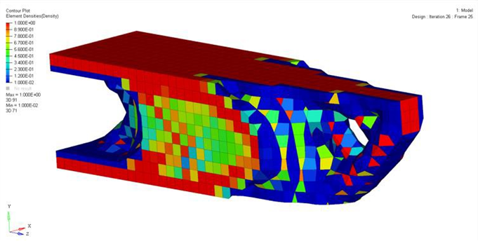
By running the
file, beam.HM.comp.cmf, as a command file in HyperMesh, the elements are grouped into sets according
to their final material density values. The set labeled "0.0 - 0.1" contains all
of the elements in which densities range from 0% to 10%. The set labeled "0.1 -
0.2" contains all of the sets in which densities range from 10% to 20%. The
elements in the sets that have material densities less then 30% are masked so
that the solution is easier to visualize. The material densities of the
remaining elements are plotted. Figure 1. Finite Element Model of a Cantilever Beam
This example is analyzed in the one-file setup with the file,
beam.fem. The OptiStruct batch
job is submitted using the command shell script, % optistruct
beam.
Results
The optimization runs for 20 iterations. The results are requested in HyperMesh binary format and written to the file,
beam.res. The shape of the solution at the final iteration
is visualized by creating an assign plot of the density results at the 20th
iteration in the HyperMeshContour panel. By removing components labeled "0.1 - 0.2", "0.2
- 0.3", "0.3 - 0.4", and "0.4 - 0.5" from the display, a concept of the optimized
beam can be visualized. Figure 2. OptiStruct Results Thresholds at 25%