OS-E: 0820 Air Conditioner Bracket
The air conditioner bracket is an optimal topology structure generated under both linear static stiffness and modal frequency response. Shell elements are used to ensure that the bracket is manufacturable using a casting process.
Model Files
Model Description
A concentrated mass, M, is used to model the air conditioner unit connected to the mounting bolts by beam elements. Shell elements close to the mounting bolt and engine bolt connections (shown as darker elements) are moved to a non-design component. The model is constrained at two engine mounting bolts that are fixed for all displacements and rotations except for the rotation perpendicular to the plane of the bracket. The belt tension load is applied at the node representing the air conditioner bracket.
DESOBJ = 1
DESGLB = 2
$
SUBCASE       1
 SPC    =    1
 LOAD   =    2
$
 WEIGHT =  1.0
$
SUBCASE       2
 SPC    =    2
 METHOD =    2
$
 MODEWEIGHT 1 1.0
 MODEWEIGHT 2 1.0
 MODEWEIGHT 3 1.0
$
NORM = 40000.0BEGIN BULK
$
DRESP1,1,freqstat,COMB
DRESP1,2,volfrac,VOLFRAC
DCONSTR,2,2,,0.3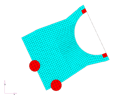
ITERATION   0

Subcase  Weight      Compliance                               Weight*Comp.
  1     1.000E+00         2.573592E+01                             2.573592E+01
                                                           ----------------
Sum of Weight*Compliance                                      2.573592E+01

Subcase   Mode        Weight     Frequency      Eigenvalue    Weight/Eigen
  2         1      1.000E+00   3.129449E+00   3.866299E+02   2.586453E-03
  2         2      1.000E+00   4.035579E+01   6.429414E+04   1.555352E-05
  2         3      1.000E+00   8.710232E+01   2.995154E+05   3.338726E-06
  2         4      0.000E+00   1.203149E+02   5.714770E+05   0.000000E+00
  2         5      0.000E+00   1.513964E+02   9.048794E+05   0.000000E+00
                                              -----------------

(Sum of Weight/Eigenvalue) / Sum of Weights       8.684483E-04
Mode Normalization Factor                         x  4.000E+04
                                              -----------------
Eigenvalue total weight                           3.473793E+01
Compliance total weight                           2.573592E+01
                                              -----------------
Objective Function                                6.047386E+01
This
example is analyzed in the one-file setup with the file, acbrack.fem.
The OptiStruct batch job is submitted using the command shell
script, % optistruct acbrack.
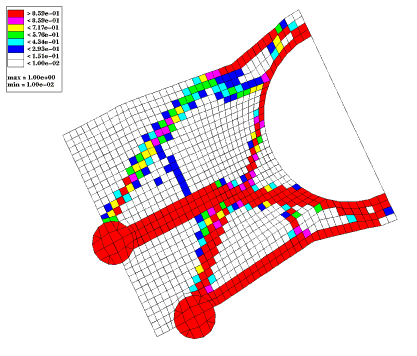
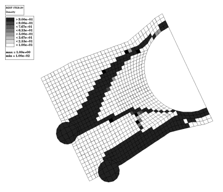
Results
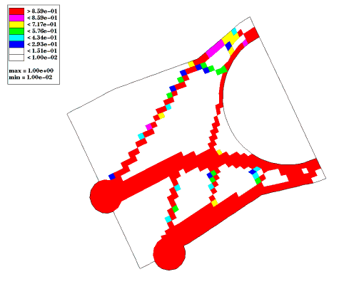
Two thick ribs extend from the engine bolts to the lower air conditioner attachment and one thin rib extends from the middle of the upper main rib to the upper air conditioner attachment. There is webbing between the two main ribs and a wide, half-height rib running through the upper half of the design space.
Many elements did not converge to either 100% dense or 0% dense. These elements can be forced toward 0% and 100% by increasing the discreteness parameter. This solution is acceptable because webbings and half-height ribs are manufacturable within a casting process.
Optimized models for linear static and frequency are analyzed separately.