OS-E: 0830 Multi-Model Optimization (MMO) – Pattern Repetition of an Excavator Arm
Multi-Model Optimization is demonstrated in this Excavator example using Topology optimization design variables that are linked between the two models.
Model Files
Model Description
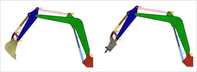
Model 1 consists of an excavator bucket and Model 2 is fitted with a hammer. The operational loading involves different number and types of subcases for each model. There are three linear static subcases in Model 1 and four linear static subcases in Model 2 that simulate the possible boundary conditions encountered during operation.
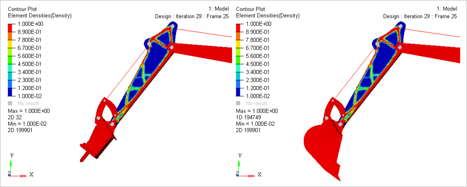
The Excavator arm is selected as the design space for Topology Optimization. Each arm is modeled as a pair of PSHELL element plates. The Topology Optimization setup is two DTPL entries (1 main and 1 secondary) with Pattern Repetition in each model to replicate the design from one plate to the other. One plate is selected as the Main and the second plate is the Secondary in each model.
For excavator design, if the bucket section is intended to be versatile and can incorporate multiple tool sets (bucket, hammer, and so on), then the rest of the excavator structure should be designed to operate under a variety of different boundary conditions. Specifically, in this case, focus on designing an excavator arm that is optimized for both the bucket and hammer configurations.
This simulation is not straightforward in individual model based Topology Optimization since each separate run will result in an optimized design for the arm that is suited for the corresponding specific configuration and use-case.
- FE Model
- Base and Joints
- CHEXA
- Cylinders
- CBEAM
- Arm, Bucket, and Boom
- CQUAD4
- MAT1
- Young’s Modulus
- 2.1E5
- Poisson's Ratio
- 0.3
- Initial Density
- 7.9E-9
- Optimization Type
- Topology Optimization
- Responses
- Weighted Compliance (WEIGHT = 1.0)
- Objective
- Minimize Weighted Compliance
- Constraints
- Volume Fraction (VOLFRAC is constrained at 0.3)
Multi-Model Optimization is a MPI-based parallelization method, requiring
OptiStruct MPI executables and MPI installation of choice
for it to run. The OptiStruct MPI executables are included,
additionally MPI installations are also available in the Solvers installation
(mpi folder within the Altair home
directory). Existing solver decks do not need any additional input, can be easily
included, and are fully compatible with the MMO mode. MMO allows greater flexibility to
optimize components across structures. The -mmo run option can be used to
activate Multi-Model Optimization in OptiStruct.
The first step is setting up the individual topology optimization models and testing them individually to determine if there are any errors or important warnings during runtime.
$
ASSIGN,MMO,bucket,excavator_bucket.fem
ASSIGN,MMO,hammer,excavator_hammer.fem
$
BEGIN BULK
$
ENDDATALinked design variables and domains should be identical in all respects (except for the COORD and SCALE continuation lines). The applied design parameters and manufacturing constraints should match in all models. This restriction does not apply to unlinked domains. Additionally, to facilitate internal pattern repetition, a COORD continuation line is required on the corresponding design variable or domain entry (DTPL, DSIZE, and so on). This allows identification of the location and direction of the repeated pattern across linked design domains.
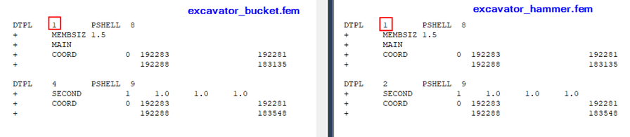
The design domains are linked as:
For Model 1, the DTPL entries with ID’s 1 and 2 and for Model 2, the DTPL entries with ID’s 1 and 4 are designated MAIN and corresponding SECOND pairs. This is used for pattern repetition within each model (NOT across models) and is not related to MMO. Such pattern repetition within each model is, of course, optional and depends on the use-case. In the current model, the two plates of the design space is required to have matching patterns so it can be manufactured easily.
The COORD continuation line allows the identification of the anchor point and mapping of the design among multiple models. This continuation line is mandatory. If individual pattern repletion is not setup (via MAIN/SECOND) in all models, you are required to specify the COORD continuation line independent of the MAIN/SECOND continuation lines.
-np) is
determined by the number of models. -np should be set equal to total
number of models plus one. In the current run, the main file is named
main.fem and the multiple models are named
excavation_hammer.fem and
excavation_bucket.fem. The
-mmo run option is required to identify an MMO run. Since there are two
models for optimization, the run option -np should be set to 3. Intel MPI
is automatically selected by default. This example is illustrated as a Windows GUI run; to
run this model via the command line on Windows or Linux, refer
to Multi-Model Optimization in the User Guide.
Results