OS-T: 2005 Design Concept for a Structural C-Clip with Minimum Member Size Control
In this tutorial you will setup a topology optimization problem that applies the technique of minimum member size control on the elements of the model to achieve a discrete solution.
Performing topology optimizations early in the conceptual design stage results in the generation of a good baseline design and contributes to a shorter design cycle. One challenge with post-processing topology optimization results is that the results may have several intermediate density elements or checkerboard patterns which can be interpreted either as solid members or as a void. If these semi-dense elements are interpreted as thin members, the final design is harder to manufacture.
OptiStruct offers the minimum member size control method which provides some control over member size in the final topology designs by defining the least dimension required in the final design. It helps achieve a discrete solution by eliminating the intermediate density elements and checkerboard density pattern, resulting in a discrete and better-reinforced structure, which is easier to interpret and also easier to manufacture.
Launch HyperMesh and Set the OptiStruct User Profile
-
Launch HyperMesh.
The User Profile dialog opens.
-
Select OptiStruct and click
OK.
This loads the user profile. It includes the appropriate template, macro menu, and import reader, paring down the functionality of HyperMesh to what is relevant for generating models for OptiStruct.
Import the Model
-
Click .
An Import tab is added to your tab menu.
- For the File type, select OptiStruct.
-
Select the Files icon
 .
A Select OptiStruct file browser opens.
.
A Select OptiStruct file browser opens. - Select the cclip_complete.fem file you saved to your working directory.
- Click Open.
- Click Import, then click Close to close the Import tab.
Apply Minimum Member Size Control Parameter
Minimum member size control will be applied to achieve a discrete solution.
-
Click inside the modeling window, then press
F4.
The Distance panel opens.
- Select the two nodes subpanel.
-
Measure the distance between nodes on an element.
- Using the N1 selector, select any node.
- Using the N2 selector, select another node on the same element.
-
Measure the distance between nodes on other elements to obtain the average
element size.
The average element size for this model is about 2.5.Note: It is recommended that the MINDIM value be three times larger than this average element size unless the element's mesh is aligned; in which case it can be two times larger.
- Click return to go back to the Analysis page.
- From the Analysis page, click optimization.
- Click topology.
- Select the parameters subpanel.
- Click review.
- Click desvar= and select shells.
- Click the toggle next to minmemb off and select mindim=, then 5.
-
Click update.
A minimum member size control has been applied on this topology optimization problem.
- Click return twice to go back to Analysis page.
Run the Optimization
- From the Analysis page, click OptiStruct.
- Click save as.
-
In the Save As dialog, specify location to write the
OptiStruct model file and enter
cclip_complete_min_member for filename.
For OptiStruct input decks, .fem is the recommended extension.
-
Click Save.
The input file field displays the filename and location specified in the Save As dialog.
- Set the export options toggle to all.
- Set the run options toggle to optimization.
- Set the memory options toggle to memory default.
- Click OptiStruct to run the optimization.
- Click Close.
The result files load automatically into HyperMesh and HyperView on completion of the run, so you can proceed directly to the post-processing step.
View an Iso Value Plot of Element Densities
-
From the OptiStruct panel, click HyperView.
HyperView launches inside of HyperMesh Desktop, and opens the session file cclip_complete_min_member.mvw which contains two pages with the results from two files.
- Page 2
- Displays the file cclip_complete_min_member_des.h3d, which contains the Optimization history results (element density).
- Page 3
- Displays the cclip_complete_min_member_s1.h3d, which contains the Subcase 1 results; initial and final (displacement stress).
- Verify that you are on page 2.
-
In the Results Browser, under the load case section, select
Design and the last iteration listed to review the
optimized iteration result.
Figure 1. 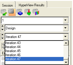
- On the Standard Views toolbar, click XY Top Plane View to set the correct view.
- From the menu bar, click .
- In the panel area, set Result type to Element Densities.
- Click Apply.
- In the Current value field, enter 0.3.
-
Compare the results to the one you achieved in the previous optimization
without the application of minimum member size control, OS-T: 2000 Design Concept for a Structural C-Clip.
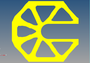
The iso value plot displayed is similar to the one previously achieved. The smaller members in the original iso surface plot are replaced by a more discrete rib pattern. This design is easier to manufacture.
Figure 2. Iso Value Plot of Element Densities