You will setup the model in HyperMesh, and run the
Topology optimization job with OptiStruct.
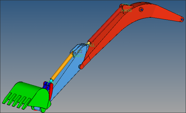
The Objective of the optimization is to maximize the stiffness of the Lower arm of an
excavator model, while keeping the mass to less than an allowable value. The model
units are kg, N, m and s.Figure 1. Excavator Model
The optimization problem for this tutorial is stated as:
Objective
Minimize the maximum compliance in an ESL loadstep.
Constraints
Upper bound on volume fraction.
Design Variables
Element density of elements in the lower arm (flexible body)
component.
Launch HyperMesh and Set the OptiStruct User Profile
Launch HyperMesh.
The User Profile dialog opens.
Select OptiStruct and click
OK.
This loads the user profile. It includes the appropriate template, macro
menu, and import reader, paring down the functionality of HyperMesh to what is relevant for generating models for
OptiStruct.
Open the Model
Click File > Open > Model.
Select the Excavator_MBD.hm file you saved to
your working directory.
Click Open.
The Excavator_MBD.hm database is loaded
into the current HyperMesh session, replacing any
existing data.
Submit the Job
The model already
has the excavator MBD analysis set up with all the bodies defined as rigid
bodies..
From the Analysis page, click the OptiStruct
panel.
Figure 2. Accessing the OptiStruct Panel
Click save as.
In the Save As dialog, specify location to write the
OptiStruct model file and enter
excavator_MBD_analysis for filename.
For OptiStruct input decks,
.fem is the recommended extension.
Click Save.
The input file field displays the filename and location specified in the
Save As dialog.
Set the export options toggle to all.
Set the run options toggle to analysis.
Set the memory options toggle to memory default.
Clear the options field.
Click OptiStruct to launch
the OptiStruct job.
If the job is successful, new results files
should be in the directory where the excavator_MBD_analysis.fem was written. The excavator_MBD_analysis.out file is a good place to look for error messages that could help
debug the input deck if any errors are present.
View the Results
When the message ANALYSIS COMPLETED is received in the dialog,
close the dialog.
From the OptiStruct panel, click HyperView.
The results for the current run automatically load into HyperView.
From the Animation toolbar, click
to start the animation and review the MBD model.
On the Page Controls toolbar, click
to delete the page, close HyperView, and return to
HyperMesh.
Set Up the Optimization
Change the Rigid Body into a Flexible Body
In this step you define the topology optimization on the body, Lower_Arm. It was originally
modeled as a rigid body and needs to be converted to a flexible body for the
optimization.
From the Analysis page, click the bodies
panel.
Select the update subpanel.
Double-click body= and select
Lower_Arm.
Click review.
The lower arm component is highlighted. Body type PRBODY
is shown for type=, indicating that lower arm is modeled as
a rigid body. You will update this body to a flexible body
type, and also define topology optimization on this
body.
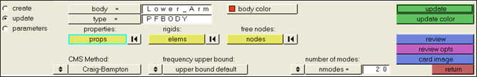
Click type= and select
PFBODY.
In the nmodes= field, enter 20.
This increases the number of modes included in the CMS method
to 20.Figure 3. Updating Body Type for Lower_Arm
Click update.
A message appears in the lower left corner to indicate
that the body has been update to a new type.
Click return.
Create Topology Design Variables
From the Analysis page, click optimization.
Click topology.
Select the create subpanel.
In the desvar= field, enter L_Arm_Topology.
Set type: to PSOLID.
Using the props selector, select lowerarm.
Click create.
Update the design variable's parameters.
Select the parameters subpanel.
Toggle minmemb off to mindim=, then enter
0.05.
Click update.
Click return.
Create Optimization Responses
From the Analysis page, click optimization.
Click Responses.
Create the volume fraction response.
In the responses= field, enter Volfrac.
Below response type, select volumefrac.
Set regional selection to by entity and no
regionid.
Using the props selector, select lowerarm.
Click create.
Create the compliance response.
In the response= field, enter Comp.
Below response type, select compliance.
Set regional selection to total and
no regionid.
Click create.
Click return to go back to the Optimization panel.
Create Design Constraints
Click the dconstraints panel.
In the constraint= field, enter Vol_Constr.
Click response = and select Volfrac.
Check the box next to upper bound, then enter
0.5.
Click create.
Click return to go back to the Optimization panel.
A constraint is defined on the response Volfrac. The constraint will force the volume fraction
used in the design space to be less than 0.5.
Define the Objective Reference
From the Analysis page, Optimization panel, click the
obj reference panel.
In the dobjref= field, enter MAX_Compin.
Select pos reference, and enter 1.0.
Select neg reference, and enter -1.0.
Click response and select Comp.
Set the loadsteps selection option to all.
This ensures the design objective reference includes
compliances from all the load steps that are calculated by the ESL
method.
Click create.
Click return to go back to the Optimization panel.
Define the Objective Function
Click the objective panel.
Verify that minmax is selected.
Click dobjrefs and select MAX_Comp.
Click create.
Click return twice to exit the Optimization panel.
Save the Database
From the menu bar, click File > Save As > Model.
In the Save As dialog, enter excavator_MBD_Topology.hm for the file name and save it to your
working directory.
Run the Optimization
From the Analysis page, click OptiStruct.
Click save as.
In the Save As dialog, specify location to write the
OptiStruct model file and enter
excavator_MBD_Topology for filename.
For OptiStruct input decks,
.fem is the recommended extension.
Click Save.
The input file field displays the filename and location specified in the
Save As dialog.
Set the export options toggle to all.
Set the run options toggle to optimization.
Set the memory options toggle to memory default.
Click OptiStruct to run the optimization.
The following message appears in the window at the completion of the
job:
OPTIMIZATION HAS CONVERGED.
FEASIBLE DESIGN (ALL CONSTRAINTS SATISFIED).
OptiStruct also reports error messages if any exist. The
file excavator_MBD_Topology.out can be opened in a
text editor to find details regarding any errors. This file is written to the
same directory as the .fem file.
Click Close.
View the Results
When the message OPTIMIZATION HAS CONVERGED is
received in the command window, close the DOS window.
From the OptiStruct panel, click
HyperView.
The results are load into HyperView.
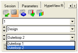
In the Results Browser, select the final
Outerloop iteration to load the optimized topology
results.
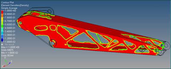
Figure 4.
From the Results toolbar, click to open the Iso Value panel.
Set the Result type to Element densities
(s).
Click Apply.
Only the elements that have elemental density higher
than what is shown Current value field display.Figure 5.
Change the density threshold.
In the Current value field, enter
0.5.
Under Current value, move the slider.
Set Show values to Above.
In the Model Browser, Component folder,
right-click on Lower_Arm and select
Isolate from the context menu.
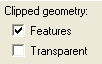
In the Iso Value panel, under Clipped geometry, select Features
to visualize the complete design space.


 to start the animation and review the MBD model.
 to delete the page, close HyperView, and return to
HyperMesh.
to delete the page, close HyperView, and return to
HyperMesh.
 to open the Iso Value panel.