OS-T: 2090 Extrusion Constraints
In this tutorial you will use the extrusion constraints method to perform an optimization problem with extrusion constraints to obtain a constant cross section along a given path, particularly in the case of parts manufactured through an extrusion process.
By using extrusion manufacturing constraints in topology optimization, constant cross-section designs can be obtained for solid models, regardless of the initial mesh, boundary conditions, or loads.
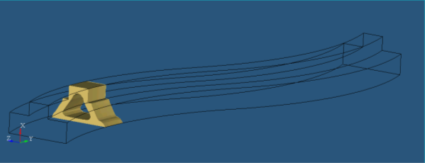
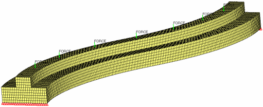
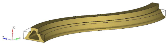
This tutorial show the steps involved in defining topology optimization over a curved beam, simulating a rail, over which a vehicle is moving. Both ends of the beam are supported. A point load is applied over the length of the rail in seven independent load cases, simulating the movement of the vehicle. The rail should be manufactured through extrusion. The steps taken to define the topology design space, the extrusion-manufacturing constraints and the optimization parameters (responses, objective and constraints) using HyperMesh are shown.
The DTPL (Design Variable for Topology Optimization) card is used for this optimization.
In this tutorial, you will perform topology optimization on a curved beam so that the extruded rail will be stiffer and have less material.
- Objective
- Minimize weighted compliance.
- Constraints
- Volume fraction < 0.3
- Design Variables
- The density of each element in the design space.
Launch HyperMesh and Set the OptiStruct User Profile
-
Launch HyperMesh.
The User Profile dialog opens.
-
Select OptiStruct and click
OK.
This loads the user profile. It includes the appropriate template, macro menu, and import reader, paring down the functionality of HyperMesh to what is relevant for generating models for OptiStruct.
Import the Model
-
Click .
An Import tab is added to your tab menu.
- For the File type, select OptiStruct.
-
Select the Files icon
 .
A Select OptiStruct file browser opens.
.
A Select OptiStruct file browser opens. - Select the rail_complete.fem file you saved to your working directory.
- Click Open.
- Click Import, then click Close to close the Import tab.
Set Up the Optimization
Create Topology Design Variables
In this step you will create the topology design space definition, design_solid. All elements organized in this design property collector will be included in the design space.
- From the Analysis page, click optimization.
- Click topology.
- Select the create subpanel.
- In the desvar= field, enter design_solid.
- Set type: to PSOLID.
- Using the props selector, select new_solid.
- Click create.
Define Extrusion Problem and Extrusion Path
-
Display the numbers for nodes 71559 and 70001 in the modeling window.
-
From the Display toolbar, click
.png) to open the Numbers panel.
to open the Numbers panel.
- Click , then enter 71559,70001 in the id= field.
- Select display.
- Click on.
- Click return.
-
From the Display toolbar, click
-
Define extrusion path.
A line of nodes starting from 71559 and ending with node 70001 should be highlighted, indicating the extrusion path.
It is not required to select as many nodes to define the curve. This is an exercise to show that the nodes by path option can also be used.
It is necessary to define a 'discrete' extrusion path by entering a series of grids.
The curve between these grids is then interpolated using parametric splines. The minimum amount of grids depends on the complexity of the extrusion path. Only two grids are required for a linear path, but it is recommended that at least 5-10 grids be used for more complex curves.Figure 2. Extrusion Path Definition 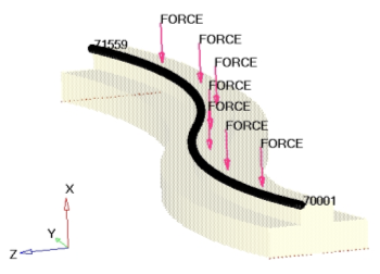
- Click return to go back to the Optimization panel.
Create Optimization Responses
- From the Analysis page, click optimization.
- Click Responses.
-
Create the volume fraction response.
- In the responses= field, enter Volfrac.
- Below response type, select volumefrac.
- Set regional selection to total and no regionid.
- Click create.
-
Create the weighted component response.
- In the responses= field, enter wcomp1.
- Below response type, select weighted comp.
- Click loadsteps, then select all loadsteps.
- Click return.
- Click create.
- Click return to go back to the Optimization panel.
Create Design Constraints
- Click the dconstraints panel.
- In the constraint= field, enter constr1.
- Click response = and select Volfrac.
- Check the box next to upper bound, then enter 0.3.
- Click create.
- Click return to go back to the Optimization panel.
Define the Objective Function
- Click the objective panel.
- Verify that min is selected.
- Click response= and select wcomp1.
- Click create.
- Click return twice to exit the Optimization panel.
Run the Optimization
- From the Analysis page, click OptiStruct.
- Click save as.
-
In the Save As dialog, specify location to write the
OptiStruct model file and enter
rail_complete_extrusion for filename.
For OptiStruct input decks, .fem is the recommended extension.
-
Click Save.
The input file field displays the filename and location specified in the Save As dialog.
- Set the export options toggle to all.
- Set the run options toggle to optimization.
- Toggle memory options to upper limit in Mb and enter 2000.
-
Click OptiStruct to run the optimization.
The following message appears in the window at the completion of the job:
OptiStruct also reports error messages if any exist. The file rail_complete_extrusion.out can be opened in a text editor to find details regarding any errors. This file is written to the same directory as the .fem file.OPTIMIZATION HAS CONVERGED. FEASIBLE DESIGN (ALL CONSTRAINTS SATISFIED). - Click Close.
View the Results
Load Results File and Post-Process
- From the OptiStruct panel, click HyperView.
-
In the Results Browser, select the last iteration
listed.
Iteration 0 is selected by default, which shows your results at the beginning of the optimization. The last iteration shows the final analysis results for this optimization.
Figure 3. 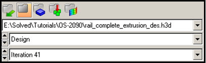
-
From the Results toolbar, click
 to open the Iso Value panel.
- Set the Result type: to Element Densities.
- Click Apply.
- In the Current value field, enter 0.3.
- Click Apply.
View a Section Cut of the Extrusion Component
-
On the Display toolbar, click
 to open the Section Cut panel.
- Click Add to create a new section cut.
- Set Define plane to Y Axis.
- Using the Base selector, click on any corner at the center of the model.
- Click Apply.
- Move the slider under Define plane to scroll though the model.
- Under Display options, use the slider bar next to Width to change the width of the cross section.