
Adaptive Perfectly Matched Layer Method for Exterior Acoustics
Exterior acoustics is the modeling of sound propagation in the unbounded domain. Adaptive Perfectly Matched Layer (APML) is an important method to modeling these domains. APML is supported for Direct and Modal Frequency Response Analysis.
- Acoustic waves at the interface do not get reflected.
- Waves which pass through this layer are attenuated.
Supported Solutions
- Direct Frequency Response Analysis
- Modal Frequency Response Analysis
- SMP runs
- DDM runs
Input
- Fluid material properties (bulk modulus, speed of sound, fluid density) can be specified for the fluid elements on the MAT10 Bulk Data Entry.
- Pole location (origin of the acoustic disturbance) is automatically calculated (this is different in IE method, where the pole location should be manually specified). For APML, if a user-defined pole location is required then the XP, YP, and ZP fields of the PACPML Bulk Data Entry can be used.
- The nodes defining the interface between the infinite and semi-infinite domain. This is defined as the perfectly matched layer elements (currently 3-noded CACPML3 and 4-noded CACPML4 elements are supported).
- If additional control over frequency banding is required, this can be done using either the PACPML Bulk Data Entry or by explicitly defining the frequency bands via the MESHF Bulk Data Entry.
- Reflection planes perpendicular to each axis can be defined using the XRFL, YRFL, and ZRFL fields and the reflection factors can be defined using the XFAC, YFAC, and ZFAC fields on the PACPML entry.
Modeling Guidelines
- A minimum of one layer of fluid elements should be defined on the surface of the structural domain of interest.
- The APML elements (CACPML3 and CACPML4) should only be defined on the topmost surface of the fluid elements.
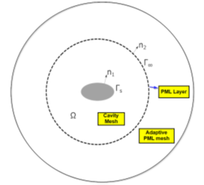
- For APML (unlike IE), the acoustic mesh and the PML elements should fully enclose the vibrating structure.
- A major aspect of the APML method is the division of the entire frequency range into smaller frequency bands. By default, the ADAPF (adaptive factor) option with a factor of 1.2 (on PACPML Bulk Data Entry) is used to generate the frequency bands. For more information, refer to Frequency Bands and Adaptive Meshing on this page.
- Sound pressure can be measured on the receiver grid points (microphone locations). For visualization of the sound pressure contour, the receiver grids should be connected using PLOTEL elements. For more information, refer to Output on this page.
- A source is generally a structure that is excited by a load, which can also be a fluid grid with SLOAD.
- The normals of the APML elements (CACPML3 and CACPML4) mesh layer should point outward and away from the acoustic source.
Modeling Checklist
- The pole is the source/origin of the acoustic disturbance. For APML, unlike IE, the pole location is automatically calculated.
- While using modal frequency response, the modal space must contain enough modes so as to capture the mechanics of the structure and acoustic cavity appropriately. A good starting point for the upper-bound in the EIGRL/EIGRA Bulk Data Entry is about 2 to 2.5 times the maximum frequency. It is also your responsibility to ensure convergence with regard to the number of modes.
- In accordance with the modeling guidelines, exterior acoustics is appropriately simulated by enclosing the entire vibrating structure with an acoustic cavity mesh and further adding a layer of PML elements on this enclosed acoustic cavity mesh. The surface of the acoustic cavity mesh on which the layer of PML elements exist should be as smooth as can be allowed without any discontinuities.
- Pressure output calculations at far-field locations should be correctly requested by ensuring that the GRID Bulk Data Entry at the microphone location belongs to the domain of the acoustic media (CD = -1).
- The generations of the interface between the fluid and structure and the rigid fluid interface (at any acoustically rigid boundaries) should be verified. This is output just after starting an OptiStruct run in the .interface file and can be quickly loaded into HyperMesh to visualize the interfaces.
- The material properties in the MAT10 Bulk Data Entry referenced by the PACPML Bulk Data Entry should have units that are consistent with the existing structural model. For example, kg-m-s (SI) or Ton-mm-s.
- You can also verify the results of the analysis by ensuring the results between direct and modal frequency response are in close agreement.
Frequency Bands and Adaptive Meshing
Frequency bands are automatically generated based on the options defined on the PACPML Bulk Data Entry. Frequency band generation is a key reason for improved performance efficiency of the APML method over Infinite Elements (IE).
With Infinite Elements, there are no frequency bands, so the IE semi-infinite mesh domain, which is internally calculated, is the same for the entire loading frequency range. Therefore, a single mesh domain has to account for the entire loading frequency range. So the thickness of the internal IE mesh domain would have to be large to account for the lowest frequency of the range, and at the same time the mesh density would have to be high to account for the highest frequency (lowest wavelength) of the range. This leads to a thick mesh domain with a very fine element mesh.
For the APML method, the full loading frequency range is divided into smaller frequency bands so that each adaptive mesh within a particular frequency band only has to account for the lowest and highest frequencies of that band. This leads to a manageable thickness of the PML mesh layer and mesh density within the layer.
Adaptive meshing is automatically carried out via a lightweight SimLab mesher to generate the domain of the perfectly matched layer. No additional settings are required as this mesher is automatically active when required during the run.
It may be inefficient to generate a single PML mesh for the entire frequency range, as this mesh would be constrained to handle the full range of loading frequencies (from the lowest to the highest). A single mesh which handles the complete range of frequencies may lead to a very thick PML mesh layer and at the same time, a very fine mesh.
It is best practice to divide the frequency range for mesh generation into multiple frequency bands. Likewise, it is not an efficient practice to generate one PML mesh for every single frequency of analysis.
- APML Feature
- Control Option
- Frequency Banding
- ADAPF (default = 1.2) on PACPML.
- PML Mesh Density
- ESBYL on PACPML (number of elements per minimum wavelength in a frequency band. Default = 4).
- PML Mesh Thickness
- TBYL on PACPML (Ratio of thickness of each PML layer to maximum wavelength of the frequency band. Default = 1.0).
- Tune PML Mesh Quality
- MESHG on PACPML (Maximum ratio between element size of a neighboring element and the size of a particular element. Default = 2.0).
- PML Elements
- CACPML3 and CACPML4 elements.
- Fluid Material Properties
- MAT10 material.
- PML Element Formulation
- MODINT on PACPML.
Output
Sound Pressure (DISP), Acoustic Power (ACPOWER), and Acoustic Intensity (ACINT) output are supported for APML analysis. They are available for acoustic direct and modal frequency response analysis in H3D and PUNCH formats.
Pressure output is requested using the DISPLACEMENT I/O Options Entry. Pressure can be requested for grid points belonging to the fluid domain of the model at external microphone locations which can be specified as GRID point sets. This is supported for H3D and PUNCH file formats.
Modal Participation factors (PFMODE) and Panel Participation factors (PFPANEL) for far-field microphone degrees of freedom are supported for APML analysis.
The far-field pressure response from APML can also be included in the PEAKOUT Bulk Data Entry to identify the peak frequencies, which can subsequently be used to generate output at these peak frequencies in the case-control section.