Edit/Review Beam Sections
Edit and review any type of beam section.
-
From the Beam Section Browser, right-click on any beam
section and select Edit.
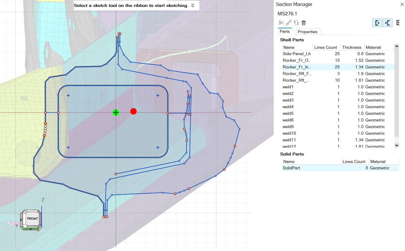
The Section Manager opens.
-
From the Section Manager, select sections from the browser list to navigate
between the sections.
Note: The name of the opened section is displayed in the top-left corner of the Section Manager.
The Section Manager invokes the Sketch ribbon. For sections from the database, the Sketch tools are grayed out, since their shape cannot be edited; otherwise, the tools are available for normal use.
Section Parts Tab
The Part tab contains information about sketch line grouping and the attributes used to compute section properties.
- Shell Parts
- A ShellPart is defined by one or more continuous curves. Not all ShellParts are necessarily connected.
- Solid Parts
- A SolidPart is defined by a group of one or more curves forming a closed loop.
Properties Tab
Whenever engines compute the section properties of the current section, they are displayed in the Properties tab.
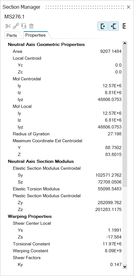
Cross Sectional Properties
The beam cross section is always defined in a y,z plane.
The x-axis is defined along the beam axis. The coordinate system you define is called the local coordinate system; the system parallel to the local coordinate system with the origin in the centroid is called the centroidal coordinate system; the system referring to the principal bending axes is called the principal coordinate system.
- Area
-
Figure 2. 
- Area Moments of Inertia
-
Figure 3. 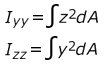
- Area Products of Inertia
-
Figure 4. 
- Radius of Gyration
-
Figure 5. 
- Elastic Section Modulus
-
Figure 6. 
- Max Coordinate Extension
-
Figure 7. 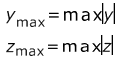
- Plastic Section Modulus
-
Figure 8. 
- Torsional Constant
-
- Solid
-
Figure 9. 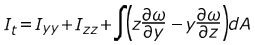
- Shell Open
-
Figure 10. 
- Shell Closed
-
Figure 11. 
- Elastic Torsion Modulus
-
- Solid
-
Figure 12. 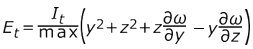
- Shell Open
-
Figure 13. 
- Shell Closed
-
Figure 14. 
- Shear Center
-
Figure 15. 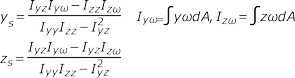
- Warping Constant (normalized to the shear center)
-
Figure 16. 
- Shear Deformation Coefficients
-
Figure 17. 
- Shear Stiffness Factors
-
Figure 18. 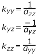
- Shear Stiffness
-
Figure 19. 
- Warping Function
-
Figure 20. 
Nastran-type Notation


Section Manager Toolbar
Access additional tools from the Section Manager toolbar.
| Tool | Function | Behavior |
|---|---|---|
| Split Parts | Splits one or more ShellParts defined by two or more curves. Enabled only if applicable ShellParts are selected. | |
| Merge Parts | Merges two or more ShellParts is they form a continuous path. Enabled only if ShellParts are selected. Limitations on t juntions. | |
| Convert | Casts SolidParts to ShellParts (or vice versa). This command
is available only for Elastic section types, since only the FEM
engine can handle both shell and solid parts. Shell parts need to form a closed loop to be converted into a Solid part. |
|
| Delete | Deletes selected Parts. | |
| Centroid | On-off state to draw centroid in sketch. | |
| Shear Center | On-off state to draw shear center in sketch. | |
| Plastic Center | On-off state to draw plastic center in sketch. |
Graphics Window
Access additional features from the graphics window.
| Item | Description |
|---|---|
| Section Centroid | |
| Shear Center | |
| Element Axis |
- From the Sketch graphical window, select a line(s) to highlight the
corresponding part(s).
Figure 26. Lines graphical selection behavior 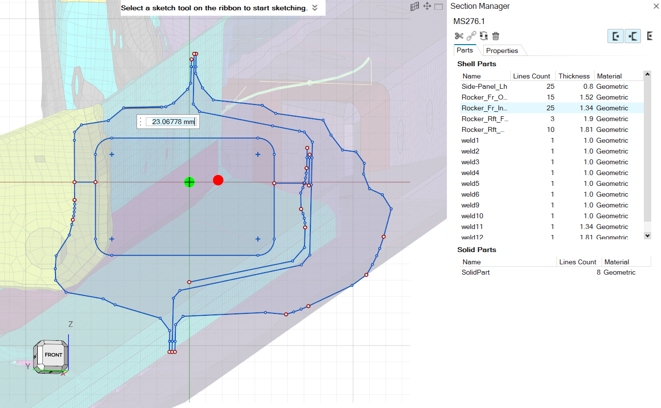
- From the Part table, select a Part(s) to highlight all corresponding sketch
lines in the graphical area.
Figure 27. Part selection from table behavior