Create Beam Sections
Create and edit beam sections of different sources and engines.
- Directly from the browser.
- From the 1D ribbon, select the Beam Section
tool.
Figure 1. Beam Section tool 
Create Standard Sections
Standard sections are predefined shapes from a database with dimensions like Channel, Hat, I, or L sections. Most of them are directly available in the solver. Section properties are evaluated using a closed form solution.
-
Set the Source to Database.
Engine will automatically set to Closed Form.
- Change the section type to the desired shape.
-
Define the beam section parameters.
Listed dimensions are based on the selected shape.
Hover your mouse over an option to view a diagram.
Figure 3. Create section from database 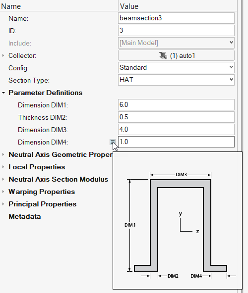
Create Generic Sections
Generic sections define sections without defining actual cross-section geometry.
- Set the Source to Generic.
- Enter desired geometric properties such as Area or Iyy/Izz.
-
For warping properties, provide:
- Shear center location Ys/Zs
- Torsional constant J
- Warping constant
The Y axis (resp Z) values define values in the beam elemental system. The origin of the local system can be defined anywhere; in this case, properly enter the coordinates of the section’s Centroid Yc/Zc.
The values mapped to the property are the components of the Centroid from Shear center, independent of the local origin used in the beamsection.
Figure 4. Create Generic section input 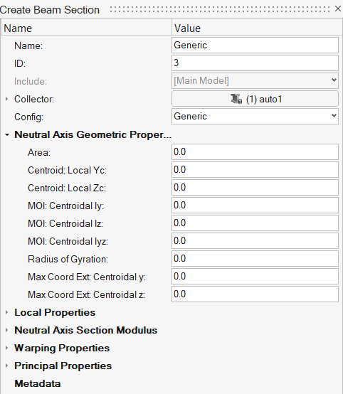
Create Shell Sections
Shell beamsections use thinwall theory and represent a section as a collection of parts.
Assign Sketch Entities
- Select a shell beam section in the browser, or create new one and set the source to shape and engine to thinwall.
- Optional:
Edit default thickness in .
Automatic sets the default thickness as 1/10th of Default size (global mesh size).
Manual lets you set your own default thickness.
- In the Entity Editor, select an existing sketch entity.
- Optional: Use the Tabular Data to change each part's name and/or thickness (size).
- Optional:
Choose a center option.
- Base point
- Uses the sketch origin as the beam section local origin.
- Centroid
- Uses calculated Centroid as beam section local origin.
- Shear Center
- Uses calculated Shear center as beam section local origin.
- Frame Center
- Place the beam section local origin at the sketch’s bounding box center.
- Lines are extracted from the assigned sketch (independent of any current geometric realization)
- Lines are split in several parts if there are either T-junctions or disconnected parts.
- Parts are defined as a collection of sketch line IDs
(Definition in tabular data).
- They have Type = Shell.
You can review and edit the realized beam section in the Section Manager.
Update Beam Sections with Sketches
The beam section entity listens to sketch updates either from direct sketch edit or parameter changes if the sketch is parametrized.
-
To update beam section shape:
- Right-click on a beam section in the browser and select Edit to open the Section Manager, which includes the Sketch ribbon.
- The beam section properties are only updated when you exit the Sketch tool.
Figure 5. Edit in the Section Manager 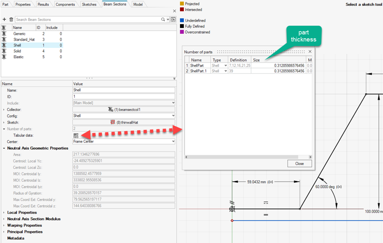
-
If the sketch has variable assigned to it (parametrized):
- From the Sketch ribbon, click the Variable Manager tool and update variable values.
- Or, use the Parameters Browser and update parameters.
- Beam sections are updated each time a variable is changed.
Figure 6. Parameter Browser and Variable Manager 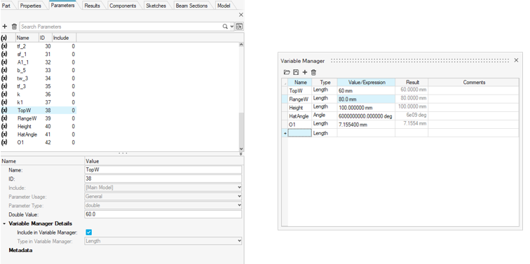
- To update the part thickness of each section part, use the dedicated column in the Section Manager.
Create Welds
Whenever parts are detected from the assigned sketch, then update relevant part names to use weld1, weld2 … This convention is used in the Inflate tool which generates surfaces and shell mesh from beams with shell beam sections; weld* parts are ignored while generating surfaces.
- Select one or several beam sections (shell only) in the beam section browser.
-
Right-click and select Auto Connect.
This tries to enforce weld creation based on part distance and thickness. There are no inputs required. The result is as per the description of the API *beamsectionautoconnectshell.
Absorb Sketches
Only orphan beam sections are absorbed.
- Select one or more beam sections in the beam section browser.
-
Right-click and select Absorb Sketch.
This option is only available if at least one of the selected beam sections is Shell or Solid. If a beam section already has a sketch assigned the nit is kept.
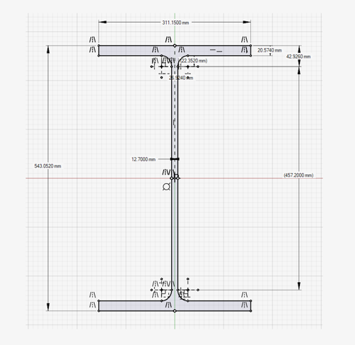
Figure 7. Sketch absorbed from shell section 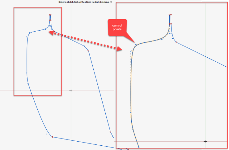
- Limitations
-
- The new data structure does not have the same limitation as the legacy Shell part structure (no part can span across the T junction in legacy); hence, the number of parts may differ after absorption. Therefore, you lose the original part distribution as well as name/thickness.
Solid Sections (Legacy)
Solid beam sections are meshed sections without considering material distribution. Also, sections are made of a single part since there is no provision for weld/contact in the engine used to evaluate the section’s properties.
Assign Sketch Entities
- Select a solid beam section in the browser.
- In the Entity Editor, select an existing sketch entity.
- Optional:
Choose a center option.
- Base point
- Uses the sketch origin as the beam section local origin.
- Centroid
- Uses calculated Centroid as beam section local origin.
- Shear Center
- Uses calculated Shear center as beam section local origin.
- Frame Center
- Place the beam section local origin at the sketch’s bounding box center.
Solid beam sections are hence populated from the mesh of the internal sketch realization:
- Surfaces are extracted from the assigned sketch.
- A disconnected region triggers multiple parts.
- This is usually not desired as Warping properties can’t be calculated.
- Geometric properties are valid.
- Parts are defined as a collection of sketch line IDs forming loops.
- Parts are meshed with an auto-calculated mesh.
Absorb Sketches
Only orphan beam sections are absorbed.
Create Elastic Sections
Elastic beam sections are 2D meshed sections. They are an extension of the legacy Solid sections.
Theory
- Solid
- Defined as a closed loop of lines.
- Shell
- Defined as lines and thickness. The thickness is used to inflate lines symmetrically to turn them into surfaces and 2D mesh them.
Material
Elastic sections can account for materials per part. Only linear elastic isotropic materials are supported. The engine uses Young Modulus, Poisson ratio, and Shear Modulus to evaluate EA, EIyy, EIzz,EIyz, GJ.
In the case of multi-materials, the engine evaluates the stiffness terms, then defines an effective material (homogenized) from the various materials and their areas in the section (it is possible to provide a target material to the engine). Section Centroid is the material weighted neutral axis. Shear Center and warping properties also account for material data using elasticity theory.
- “Analysis and Design of Elastic Beams: Computational Methods, Walter D. Pilkey”
- Elastic sections evaluate stiffness terms.
- Target solvers only know about a property entity and a material entity.
- Properties store geometric data like area and second moments of inertia.
- Materials store Young/Shear moduli and Poisson ratio.
- A stiffness matrix is formed as a product of the two separate.
- It is then needed to normalize the data with the homogenized material to fit in the solver data structure.
Elastic beam sections considering material information are only available in the Section Property tool with Update beam (see Update Beam elements) as it not only creates a beam section but a property with the correct material.
Any other tools dealing with elastic sections ignore materials.
Contact
Elastic sections support multiple parts with small gaps:
- Shell type sections are first inflated based on their thickness.
- All parts are then considered for contact search between all bodies.
- Contact can be turned off.
- You can set the tolerance.
- Default (Best match) is around 80% of the average mesh
size in the section.
Keep in mind that a thickness of 4 elements is ensured during shell part inflate.
When a sketch is assigned to a beam section, default contact is always used.
Create and Edit Elastic Sections
- Create a new beam section from the browser.
-
Set the source to Shape and engine to
Elastic.
The section has no default shape, hence all properties are 0.0 like a Generic section.
- Optional:
Edit default thickness in .
Automatic sets the default thickness as 1/10th of Default size (global mesh size).
Manual lets you set your own default thickness (used for Shell parts).
- In the Entity Editor, select an existing sketch entity.
- Optional:
Choose a center option.
- Base point
- Uses the sketch origin as the beam section local origin.
- Centroid
- Uses calculated Centroid as beam section local origin.
- Shear Center
- Uses calculated Shear center as beam section local origin.
- Frame Center
- Place the beam section local origin at the sketch’s bounding box center.
- Surfaces are extracted from closed loops and considered as Solid parts with
Type = Solid.
- Disconnected regions trigger multiple Solid parts.
- Other lines (not forming closed loops) are considered as Shell parts with Type = Shell.
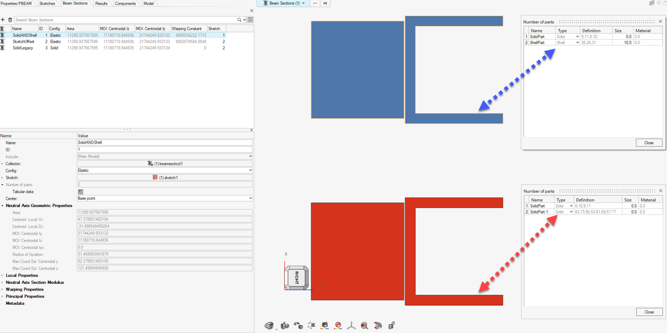
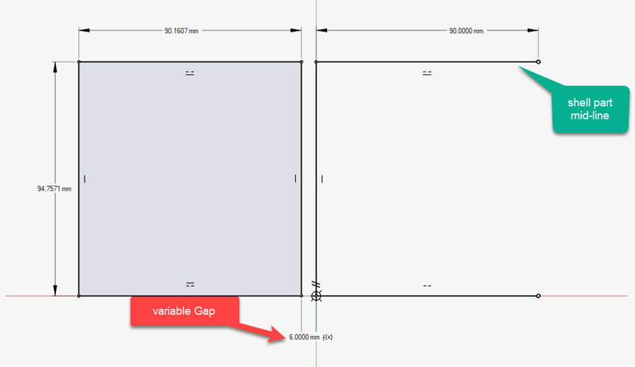
Hybrid Sketch and Contact
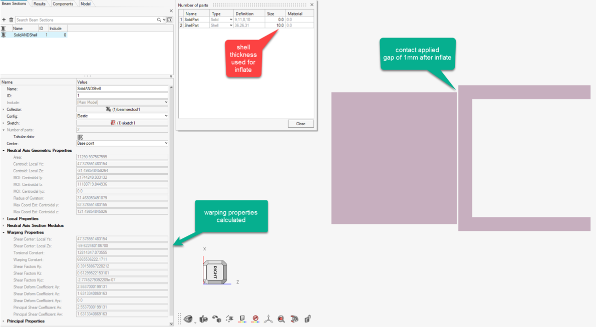
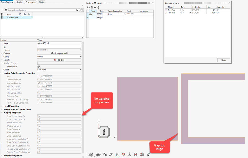
The following example (Figure 9 & Figure 12) depicts a hybrid sketch where 4 lines form a closed loop and 3 lines an open section. In this example, the Gap parameter is introduced to control distance between 2 shapes.
The closed loop is understood as a Solid part while the open section is considered a Shell part.
- In the first case, the final gap after inflating is 1.0, which falls under the tolerance; hence, a contact is created between parts. Warping properties are evaluated.
- In the second case the final gap is 5.0, which is too large for this model; hence, no warping properties are available.
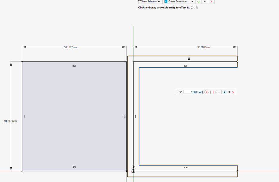
Solid Sketch
Using the same original sketch, you can use the Sketch Offset tool to create a symmetric offset of the open section to turn it into a closed loop of lines. Click and drag the offset to play with the solid section's thickness or enter a precise value (Figure 12).
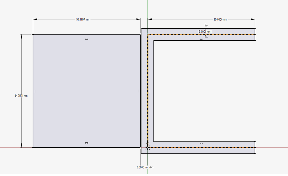
- the top beam has a property referring to a hybrid sketch with a shell part of thickness 10.0.
- the bottom beam has a property referring to the offset sketch from Figure 12.
Contact management is the same in both cases (hybrid or full solid).