Visualization
Tools for visualizing orientations, ply shapes and ply layers.
Several types of visualization tools specific to composites are available.
Information that can be plotted includes:
- Composite laminate material reference orientation
- Ply fiber and matrix directions
- Ply shape
- Ply layers of 2D model shown with thickness
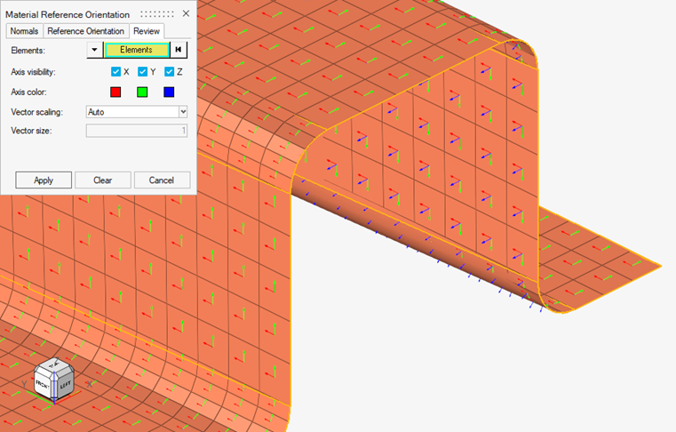
Material Reference Orientation
Material reference orientation of composite laminates.
The material reference orientation of a composite laminate defines zero degree fiber direction from which ply orientations rotate. Visualizations are performed using the Material Reference Orientation dialog.
- From the Composite Browser, right-click the white space and select from the context menu.
- In the dialog, click the Material System tab.
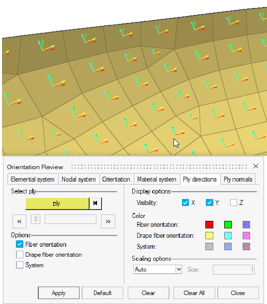
Ply Direction
Visualize ply directions.
Ply directions for both nominal fibers and draped fibers can be visualized.
- From Composite Browser, right-click the white space and select from the context menu.
- In the dialog, click the Ply directions tab.
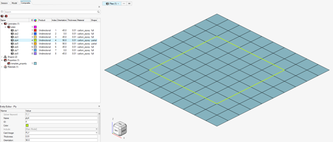
Ply Shape
Visualize ply shapes.
To visualize ply shapes boundaries of selected plies in the modeling window, select a ply entity in a browser or the modeling window. Its boundaries will be highlighted in the modeling window.
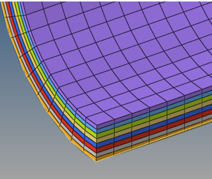
Thickness and Layers
Display thickness of ply layers.
For ply-based shell models, the thickness of each ply layer can be displayed using
the visualization options on the View Controls toolbar.
Note: Only
laminate thickness is supported for zone-based shell models. Ply layer
visualization is not supported. The recommended option is to use the Aerospace
Absorb Properties option to convert the zone properties to plies.
-
Click
 on the View Controls toolbar.
-
Set the shell thickness
option to 3D.
This will visualize the total thickness on each element.
-
Set the
ply layer and edge option to Ply layers.
This will display the individual layers within each element thickness.
Figure 4. 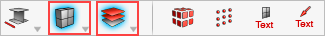
-
Click
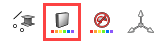 on the View Controls toolbar.
-
Set the face color
to Property.
This will color each layer according to the color of the ply.
-
From the menu bar, select and type a factor in the ply thickness factor field. Typical values range from 5 to 10.
The thickness of each ply layer is increased.
Figure 5.