Material Reference Orientation
The Material Reference Orientation tool provides several tabs to set and review x and z material reference orientations.
- Select the elements on which to set normals.
- Set the operations to apply to the elements:
- Display visualizes the current element normal direction.
- Adjust forces a consistent element normal direction. This is determined by the normal direction of the majority of selected elements.
- Reverse flips the normal direction of all selected elements.
- Use the Display option to set the visualization method.
- Color will contour the elements such that the element normal goes in the direction of the red colored side of each element.
- Vector will draw vectors in the direction of the element normal.
- Vector scaling determines whether auto or manual scaling of the drawn vectors is
used.
If Manual is selected, the desired Vector size should be entered. Note the length unit is the same as that of the model.
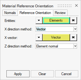
To set the x material reference direction for all elements and the z direction for
solids elements, the Reference Orientation tab should be used.
- Select the Entities on which to assign material orientation, either Elements or Properties.
- Set the X direction method. Refer to Table 1 for available methods by solver and element type.
- Angle – directly enter rotation applied on THETA field of element.
- Curve – spatially map input curves as the x direction.
- Lines/Nodes – curve which represents the desired x direction to be mapped to elements.
Flip direction - determines whether the curve provided is +x direction or -x direction.- System Axis - system and axis of system to map as x direction.
- System ID - system assigned as orientation.
- Vector - specify a vector to map as the x direction.
Table 1. Solver Angle Curve System Axis System ID Vector OptiStruct Yes Yes Yes Yes Yes Radioss No Yes No Yes Yes Abaqus No Yes Yes No No ANSYS No Yes No Yes No LS-DYNA No Shells only Shells only Shells only Shells only Nastran Shells only Shells only Shells only Shells only Shells only - Set the Z direction method.
- Element Normal – uses element z direction (can be viewed from the Normals tab). Typically, this option should be used.
- Surface Normal - aligns material z direction spatially to selected surface. Note only a single surface can be selected.
To visualize material reference directions, the Review tab should be used. Vectors
representing the x, y and z directions can be plotted and controlled.
- Select the elements on which to plot vectors.
- Select axes to plot using Axis visibility.
- Optionally specify how the axes are drawn. Axis colors can be changed from the defaults. Vector scaling determines whether auto or manual scaling of the drawn vectors is used. If Manual is selected, the desired Vector size should be entered. Note the length unit is the same as that of the model.