Structural Element
Preliminary design tools for creating and analyzing structural elements.
Analyze Plate
Use the Composite Plate Analysis dialog (Figure 1) to create and analyze a flat composite plate with parametric dimensions, a given laminate, a variety of loads, and boundary conditions.
-
From the Composite Browser, right-click white space or any
Laminate and select from the context menu.
The Composite Plate Analysis dialog opens.
Figure 1. 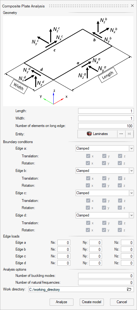
-
In the Geometry section, define the plate.
The plate is defined by giving length and width as parameters as well as the intended number of elements on the longer of the two dimensions. The default value for the latter is set to 100 to cover a wide variety of setups, but it can be set freely to another integer value, for example to create plates with very few elements.
Laminate selection is required as well. The laminate configs Ply laminate and Sublaminate are supported (for more information, refer to Laminates).
-
Select boundary conditions for all four edges of the plate.
Note: Rigid body movements must be prevented to achieve a solvable model.
- Clamped: all degrees of freedom are fixed.
- Simple roller: only translation in global z direction is fixed.
- Simple fixed: all translational degrees of freedom are fixed.
- Free: all degrees of freedom are free.
-
Define edge loads.
Note: Loads must be given as components in the directions of the global coordinate system. They are defined as total loads on the edges (as opposed to loads per unit length or constant nodal loads).
-
Set analysis options.
A linear static analysis subcase is always created. For buckling and natural frequency analysis, the number of modes and frequencies respectively can be defined. The default value 0 indicates, that this analysis subcase is not created.
-
Browse and select the Work directory.
Note: By default, a temporary directory in the home directory will be set, but it can be adjusted. Each run in the same folder will create a four-digit number sub-directory.
-
Complete one of the following actions:
- Select Create Model to run the model creation process.
- Select Analyze to run the model creation process and automatically export the deck, run it in OptiStruct, and load the results into HyperMesh.
Upon clicking Create Model or Analyze, a new parametric plate model is created on a new page. The sequence of plies of the chosen laminate in the current model and corresponding materials are copied to the new model. Plate geometry is created and meshed. A ply shape covering the plate is created and assigned to the plies. A property is created such that the laminate has its reference plane at mid-plane. Loads and boundary conditions are created in corresponding collectors. Subcases are created and output parameters set. By default the result OUTPUT parameter is set to H3D, with GLOBAL OUTPUT REQUESTS for element forces and moment, composite stresses and strains (mid-plane) enabled.If Analyze is selected, the OptiStruct solver deck will automatically be exported, run, and the result file will be imported to the new page. They can be post-processed with the Results Browser, or using the Composite Stress Toolbox.