
Mechanism Browser
Create and articulate a kinematic mechanism based on FE mesh using the Mechanism Browser.
You can undo and redo actions made in the Mechanism Browser using the Undo and Redo commands on the Restore toolbar.
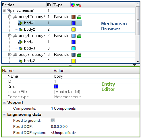
| Column | Description |
|---|---|
| Entity | Lists the mechanism, joints, bodies, and constraints in your model. |
| ID | Displays the mechanism, joints, bodies, and constraints IDs. |
| Type | Displays the joint or constraints type. |
| Color | Displays the joint and body entity colors. Body color is different from the component color set-up in the Model Browser. The body color is activated when a body is in Review mode. |
| Lock level | Displays the lock level of a joint (green = free joint, yellow = locked joint). |
Create Mechanisms
Create a mechanism.
Mechanisms are created using a manual approach only.
-
From the Mechanism Browser, right-click and select .
You will see the mechanism created with bodies as shown in the following image.
Figure 2. 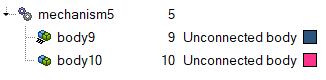
-
Set options according to the following table. Each field must be defined or
selected.
Table 1. Mechanism Builder Options Option Action Mechanism Type Select the type of mechanism, either Seat or General. Your selection will affect other options in the dialog. Mechanism Name Type the name you want to give to the mechanism after the extraction is completed. Entities Select the FE components that define the mechanism. You can choose Components, Mechanisms, Assemblies or Sets. Node Selection on Lower Track When the Mechanism Type is set to Seat, you can select nodes on the lower track components of the seat. Node Selection on Upper Track When the Mechanism Type is set to Seat, you can select nodes on the upper track components of the seat. Sliding Vector on Upper Track When the Mechanism Type is set to Seat, you can specify the translation direction of the joint defined for the seat track. Seat Track with Roller Balls When the Mechanism Type is set to Seat, you can specify whether the seat track contains roller balls. If you check this option, HyperMesh will automatically create a double slider joint for the seat track, and an additional selector for the seat track roller will appear. Track Roller Balls When the Mechanism Type is set to Seat, and Seat Track with Roller Balls is checked, this option allows you to select the roller ball components that will be defined as third body in the double slider joint. Joint Elements Select the FE elements (springs or beams) that have to be created as joints in the mechanism extraction process. Excluded Elements Select the FE elements that should be excluded from the extraction process of the mechanism. For example, nodal rigid bodies that are used to link components in the FE model but that are not physical conditions, can be selected here and will not be considered in the extraction process.
Excluded Contacts Select to exclude tied contacts that may be defined on the FE model but do not represent physical connections. This excludes them from the extraction logic. Detect Holes Select to activate the hole detection parameters. This allows you to detect joint positions by looking for concentric holes in components. Relative Search Distance When Detect Holes is checked, this option defines the distance of search for concentric holes that define a joint location. Components for Hole Search When Detect Holes is checked, this option allows you to select the components on which the hole detection must be performed. Preferred Revolute Joint Axis Type the vector that defines the revolute joint axis. This will overwrite the direction of the joint elements. Angular Tolerance Type the angular tolerance into this field. The joint axis within this angle will be overwritten by the Preferred Revolute Joint Axis value. - Assign components to bodies under the created mechanism in the Entity Editor. You can specify the options "Fix to ground," "Fixed DOF," and "Fixed DOF system."
-
After the bodies are assigned components, right-click and select both bodies to
create the desired connection type.
Figure 3. 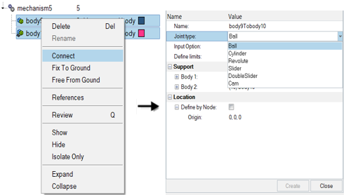
Modify the Position of Mechanisms
-
In the Mechanism Browser, right-click on a mechanism and
select Actuate Mechanism from the context menu, then choose from one of the following:
- Choose Translate to open the Entity Editor and select a Node/Constraint, give a
Direction of motion, and define the Magnitude of the translation to
apply.The Magnitude can also be modified, using the up and down arrow buttons. Moreover, you can control the increments of the operations by changing the Increment value.
Figure 4. 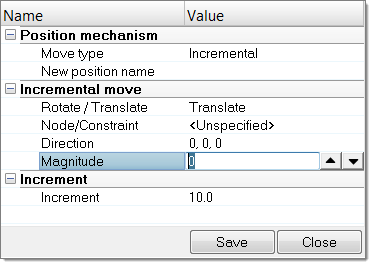
- Choose Rotate to open the Entity Editor, select a Body, define a Rotation axis, a
rotation center (Base point), and provide the Magnitude of the rotation to
apply to the body.The Magnitude can also be modified, using the up and down arrow buttons. Moreover, you can control the increments of the operations by changing the Increment value.
Figure 5. 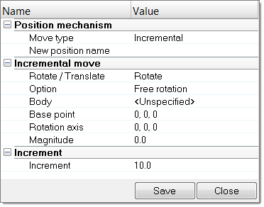
- Choose Target Point to open the Entity Editor, select a Node and define its Target
location. Click Move to calculate the position of
each body to bring the selected node to the target location or the nearest
location, depending on joints limit values.This option can be applied on a set of nodes and targets, by setting Multiple pairs to Yes.
Figure 6. 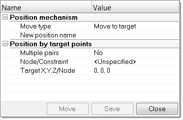
- Choose Translate to open the Entity Editor and select a Node/Constraint, give a
Direction of motion, and define the Magnitude of the translation to
apply.
-
Click Save to save the achieved position.
A name will be appended to the New position name field.
Modify the Position of Joints
- In the Mechanism Browser, right-click on a joint and select Move from the context menu.
-
Modify the position of the joint.
- In the graphics area, click-and-drag the manipulator.
Figure 7. 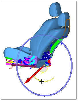
- In the Entity Editor, modify the Current angle
of the joint.
Figure 8. 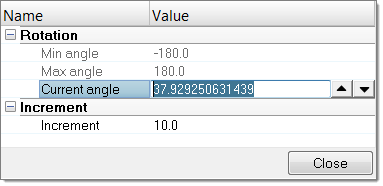
- In the graphics area, click-and-drag the manipulator.
- Change the Increment value to control the increments of the operation.