
Apply Constraints
Use the Constraints tool to hold a part so that it maintains its designated position throughout the forming process.
-
Click the Constraints tool on the
Constraints icon.

-
Click on a point, edge, face, or hole.
- Hold the Shift key as you click to create a concentrated point support.
- Hold the Ctrl key to apply the support to multiple features on the same part.
-
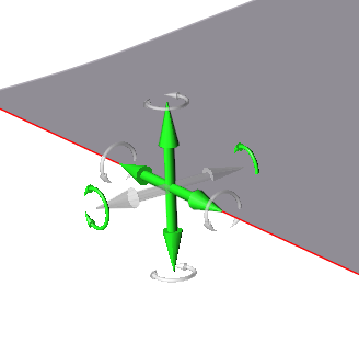
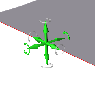
To allow translation in one or more directions for a particular support, click
on a cone for that support. A transparent axis trident appears.
-
Click on the arrows to toggle the locks on and off in those directions.
A green arrow indicates that translation is allowed in that direction, while a gray arrow indicates that it is locked.
- Right-click and mouse through the check mark to exit, or double-right-click.
Tip:
- You can edit individual supports to allow translation or rotation in one or more directions. Double-click on a support to enter editing mode.
- Once a support is created, you can move it away from the model to create a support at a distance by using the Move tool on the microdialog.
Translate or Rotate Constraints
When you create a support, translation is locked in all directions by default; you can edit individual supports to allow translation in one or more directions.
- Double-click on a support to enter editing mode.
-
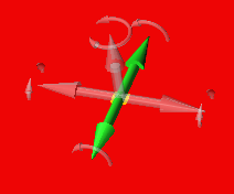
Click the clear axis arrows to enable translation for that axis.
A green arrow indicates translation or rotation is enabled.
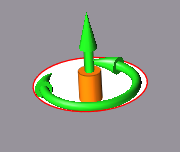
Apply a Support to a Cylindrical Hole
Supports applied to a cylindrical hole are a special case, and have different properties from supports applied to a point, edge, or face.
-
Click the Constraints tool on the
Constraints icon.
-
Click on the interior of a hole.
- Hold the Shift key as you click to create a concentrated point support.
- Hold the Ctrl key to apply the support to multiple features.
-
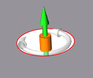
To allow translation or rotation, click on the red support cylinder.
Transparent graphical handles appear.
-
Click on the arrows to toggle the locks on and off in those directions.
A green arrow indicates that translation or rotation is allowed in that direction, while a gray arrow indicates that it is locked.
- Right-click and mouse through the check mark to exit, or double-right-click.
Microdialog Options
Double-click a constraint to enter editing mode, which opens the Support microdialog.
|
|
Translate or rotate the support using the Move tool. Use to place a support at a distance. |
|
|
Align the support normal (perpendicular) to the face. |
|
|
Align the support normal to the draw direction. |
|
|
Align the support to the global axes. |