Since version 2026, Flux 3D and Flux PEEC are no longer available.
Please use SimLab to create a new 3D project or to import an existing Flux 3D project.
Please use SimLab to create a new PEEC project (not possible to import an existing Flux PEEC project).
/!\ Documentation updates are in progress – some mentions of 3D may still appear.
Advice of utilization / limitations
Introduction
This section reminds several information elements on the utilization conditions of the cuts and it deals with the current limitations of the software in this respect.
It is about better answering to the question: when should the cuts be located?
When should the cuts be located?
It is necessary to create the cuts whenever there is a connectivity problem, taking into account the following elements…
- it is not necessary to create a cut as the group of non connected region (with holes) is already cut by «replacing element» (plan of symmetry/periodicity, surface region…). The «replacing elements» are presented in the section below
- it is necessary to take into account the current limitations of the software (what is authorized and what is not)
The «replacing elements»
The cuts are not necessary when there are «replacing elements» that play the role of cut. These elements are presented in the tables below.
For a magnetic circuit:
- a symmetry plan of normal magnetic field type
- a periodicity plan (even / odd ?)
A surface region of the type of:
- «Air gap region»
- «Non conducting magnetic region» and of sub type:
- «quasi normal magnetic flux»
- «no restriction on the direction of the magnetic flux»
These elements are identified by the command Check Physics
Limitations in terms of construction
A cut should not be in contact with:
- a plane of periodicity / symmetry
- a face region
- the boundary between two mechanical sets: sliding surface or dissociation surface
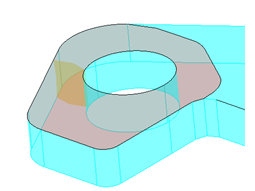
In this example, the cut on the mesh in the thickness of the device (in transparent yellow) is in contact with the surface region (parasite air gap) at the top part of the device (in transparent red).
Limitations in terms of functioning
It is not possible to solve a geometric parametric scenario when the project contains cuts of type cut on the mesh (because of the deletion / re-generation of the mesh at each time step).