Since version 2026, Flux 3D and Flux PEEC are no longer available.
Please use SimLab to create a new 3D project or to import an existing Flux 3D project.
Please use SimLab to create a new PEEC project (not possible to import an existing Flux PEEC project).
/!\ Documentation updates are in progress – some mentions of 3D may still appear.
Link regions and components: coil conductor
Introduction
With regard to the coil conductors, the user must carry out the two following operations (without particular order to respect):
- link a B1 component to the REG_B1 region
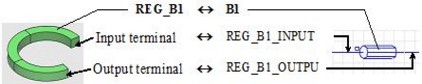
-
orient the REG_B1 region (define the input/output terminals)
(and thus implicitly define REG_B1_INPUT / OUTPUT electric terminals)
Link regions and components
To link the regions of the coil conductor type (of FE domain) to the components of the coil conductor type (of the electric circuit) follow the next procedure:
| Step | Action |
|---|---|
| 1 |
In the Physics menu:
|
| → | Division of graphic zone in two and visualization of the FE domain in
one zone and the electric circuit in the other Display of the volume regions of coil conductor type in the form of array |
| 2 |
In the array *, fill out the zone for each region:
|
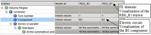
Array of coil conductors
The array corresponding to the regions of the coil conductor type is presented in the figure below.
In this array, the zones which allow the visualization of the regions (of coil conductor type) and of the electric components (of stranded coil conductor type) are showed in the figure below.
Orient wires of regions
To orient wires of a region of coil conductor type (i.e. to define its geometric input/output terminals ) follow the next procedure:
| Step | Action | |
|---|---|---|
| 1 |
In the Physics menu:
|
|
| 2 |
In the dialogue box Orient wires …:
|
|
| If external terminals | If internal terminal (double terminal) | |
| select faces describing the input terminal | select faces describing double input/output terminal | |
| → the output terminal is automatically identified | select the orientation line | |
| → | Automatic creation of the electric terminals | |
Check the links
To check the links follow the next instructions:
| To check the links of type … | edit … | and examine the field … | |||
|---|---|---|---|---|---|
| region |
|
component |
|
the regions | Component |
| geometric terminals |
|
electric terminals |
|
the electric terminals | Faces of the terminal |
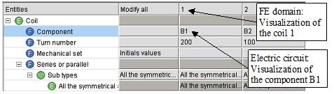
Link coils and components
To link the non meshed coils (of the FE domain) to the components of stranded coil conductor type (of the electric circuit), follow the next procedure:
| Step | Action |
|---|---|
| 1 |
Select the coils:
|
| 2 |
Activate the command:·
|
| → |
Command effect: Display in a table of non meshed coils |
| 3 |
In the array * fill out the zone for every coil:
|
Array of non meshed coils
The array corresponding to the non-meshed coils is presented in the figure below.