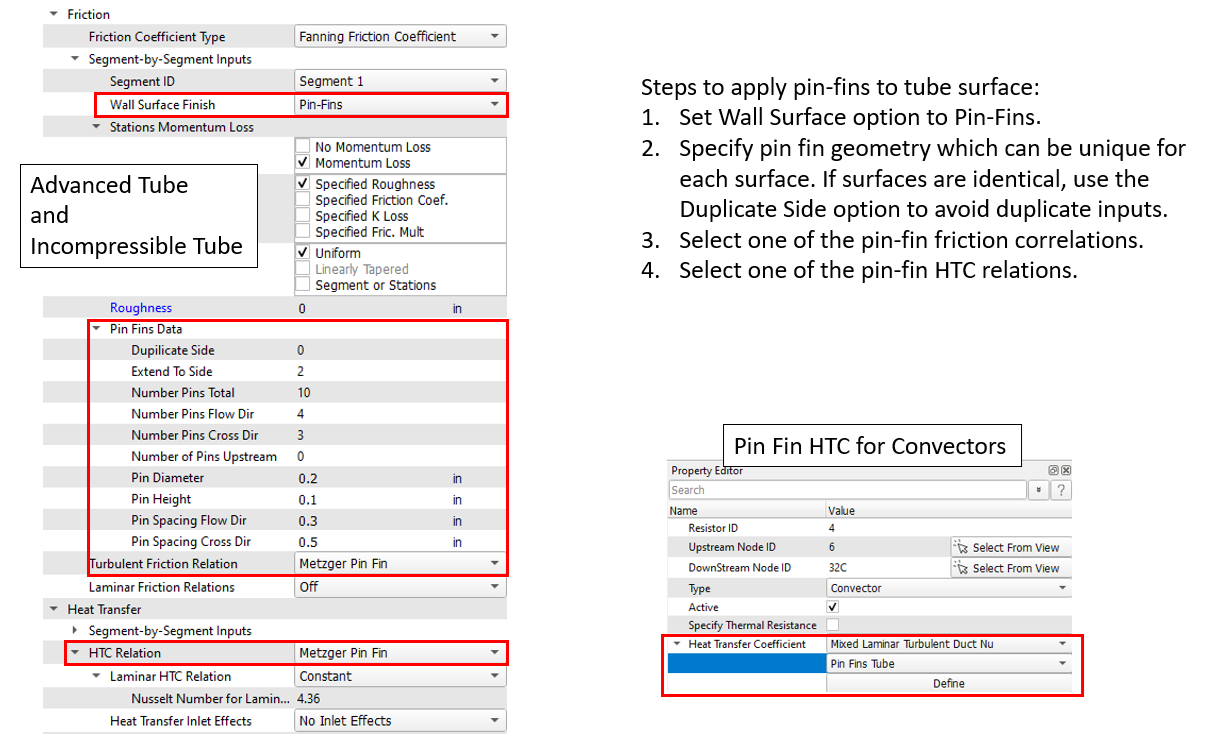
Pin Fin Tube
Description
- Type
- Mixed Laminar-Turbulent Duct Nu
- Subtype
- Pin-Fin Tube
| Index | UI Name (.flo label) | Description |
|---|---|---|
| 1 | Pin Fin Correlation (PIN_FIN_CORL) |
The HTC equation to use.
|
| 2 | Convector Area Option (CONV_AREA_OPT) |
Option to add the calculated pin-fin area to the convector
area.
|
| 3 | Flow Element (FLOW_ELM) |
ID for flow element that will be used for mass flow rate and
other correlation inputs. If AUTO, the correlation must be applied to a convector that is connected to a fluid chamber that has only one flow element entering this chamber. The ID of this flow element will be used. The element can be of almost any type, although some types will not have geometric inputs that can be obtained with the AUTO option of the remaining inputs. |
| 4 | Number Pins Flow Dir (NUM_FLOW) |
Number of pins in the direction of flow. If AUTO, use input from the FLOW_ELM. |
| 5 | Number Pins Cross Dir (NUM_CROSS) |
Number of pins in the direction perpendicular to the
direction of flow. If AUTO, use input from the FLOW_ELM. |
| 6 | Number Pins Total (NUM_TOTAL) |
Total number of pins. This will be used to calculate the pin
surface area. If AUTO, use input from the FLOW_ELM. |
| 7 | Number of Pins Upstream (NUM_UPSTRM) |
Number of pins in the direction of the flow upstream of this
current region. This will be used for the pin array inlet
effects. If AUTO, use input from the FLOW_ELM. |
| 8 | Hydraulic Diameter (HYD_DIA) |
Passage hydraulic diameter. If AUTO, use input from the FLOW_ELM. |
| 9 | Flow Area (FLOW_AREA) |
Passage flow area without the pin blockage. An area that includes the pin blockage will be calculated using the pin dimensions. If AUTO, use input from the FLOW_ELM. If the area from the flow element is not available, the passage will be assumed circular, and the hydraulic diameter will be used to calculate the area. |
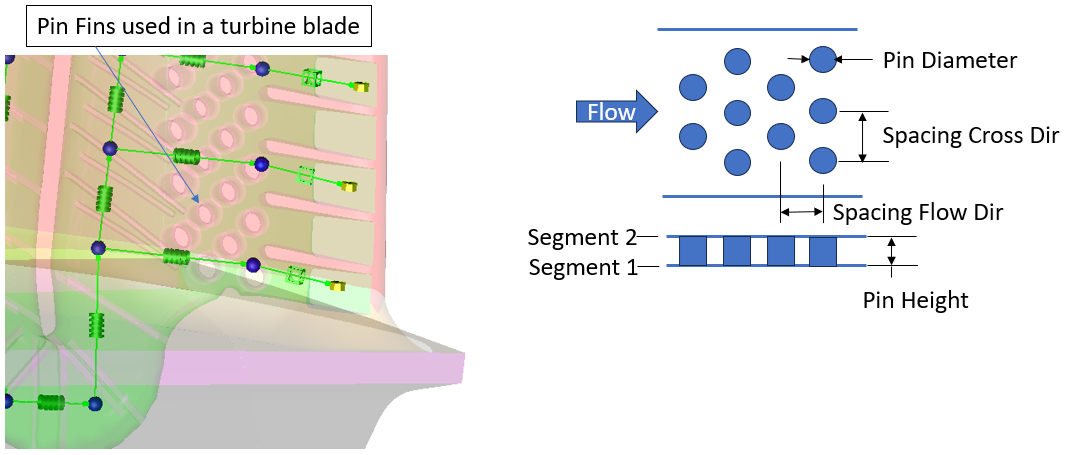
| 10 | Pin Diameter (PIN_DIA) |
The diameter of the pins. If AUTO, use input from the FLOW_ELM. |
| 11 | Pin Height (PIN_HGT) |
The height of the pins. If AUTO, use input from the FLOW_ELM. |
| 12 | Pin Spacing Flow Dir (SPC_FLOW) |
The distance between the pin centers in the flow
direction. If AUTO, use input from the FLOW_ELM. |
| 13 | Pin Spacing Cross Dir (SPC_CROSS) |
The distance between the pin centers in the direction
perpendicular to the direction of flow. If AUTO, use input from the FLOW_ELM. |
| 14 | Pins Extend Across Passage (PINS_EXTEND) |
If AUTO, use input from the FLOW_ELM. |
| 15 | Wall Roughness (WALL_RGH) |
The wall roughness. If AUTO, use input from the FLOW_ELM. |
| 16 | Inlet Row Effects (INLET_EFF) |
Option for heat transfer inlet effects.
|
| 17 | Laminar-to-Transition Re (RE_LAM) |
Reynolds number where the Laminar regime of flow ends and the
Transitional regime starts. If AUTO, RE_LAM = 900. |
| 18 | Transition-to-Turbulent Re (RE_TURB) |
Reynolds number where the Transitional regime of flow ends
and the fully Turbulent regime starts. If AUTO, RE_TURB = 1100. |
| 19 | HTC Multiplier (HTC_MULT) |
A constant multiplier to scale the value of the heat transfer coefficient obtained from the correlation. |
| 20 | Primary Coefficient (PRIM_COEF) |
Coefficient to use in the Nusselt number equation when PIN_FIN_CORL = User Defined. |
| 21 | Spacing Flow Dir Exponent (X_O_DP_EXP) |
Exponent to use in the Nusselt number equation when PIN_FIN_CORL = User Defined. |
| 22 | Cross Flow Dir Exponent (S_O_DP_EXP) |
Exponent to use in the Nusselt number equation when PIN_FIN_CORL = User Defined. |
| 23 | Reynolds Number Exponent (RE_DP_EXP) |
Exponent to use in the Nusselt number equation when PIN_FIN_CORL = User Defined. |
| 24 | Rough Ratio Coefficient (RGH_RAT_COEF) |
Coefficient to use in the Nusselt number equation when PIN_FIN_CORL = User Defined. |
| 25 | Rough Ratio Exponent (RGH_RAT_EXP) |
Exponent to use in the Nusselt number equation when PIN_FIN_CORL = User Defined. |
| 26 | Free Convection Nu (FREE_HTC) |
The equation to use for free convection blending.
If AUTO, FREE_HTC = 2. |
| 27 | Free Mixing Sign (FREE_ASSIST) |
The sign of the free and forced HTC blending.
If AUTO, FREE_ASSIST = 1. |
| 28 | Free Length Scale (FREE_LEN) |
The length scale for the free convection HTC
calculation. If AUTO, FREE_LEN = LENGTH. |
| 29 | Horizontal Free Surface Dir (FREE_SURF_DIR) |
Direction of the horizontal plate that is used if
FREE_HTC=3.
|
Formulation
- User defined (ref. 1).
This correlation uses user-defined coefficients and exponents, so it can be used with test data from other pin-fin geometries.
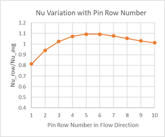
- Metzger (ref 2).
This is for staggered pin-fin arrays and smooth walls. The passage is typically narrow with the pin height close to the pin diameter. The passage shape is typically found in cooled turbine blade training edges. The base Nusselt number equation is for the average of 10 rows in the flow direction.
Limits:
- Corbett (ref 1).
This is for staggered pin-fin arrays and rough walls. The passage is typically narrow with the pin height close to the pin diameter. The passage shape is typically found in cooled turbine blade training edges. The base Nusselt number equation is for the average of multiple rows in the flow direction.
Limits:
Where:
All correlations use a Reynolds number based on the pin diameter and a flow area that includes blockage.
| Index | .flo label | Description |
|---|---|---|
| 1 | TNET | Thermal network ID, which has the convector where this correlation is used. |
| 2 | CONV_ID | Convector ID, which is using this correlation. |
| 3 | CORRLTN | The correlation identifier (METZPF, CORBPF, and so on). |
| 4 | FLOW_ELM | Flow element from input 1 or automatically selected. |
| 5 | FLOW | Mass flow rate used in the Re calculation. |
| 6 | PIN_DIA | The pin diameter. |
| 7 | PIN_HGT | The pin height. |
| 8 | NUM_FLOW | Number of pins in the flow direction. |
| 9 | NUM_CROSS | Number of pins perpendicular to the flow direction. |
| 10 | X_O_DP | Pin spacing in the flow direction/pin diameter. |
| 11 | S_O_DP | Pin spacing perpendicular to the flow direction/pin diameter. |
| 12 | RE | Reynolds number. |
| 13 | NU | Calculated Nusselt number. |
| 14 | HTC | Calculated heat transfer coefficient. |
Heat Transfer Correlation References
- Corbett, T.M., Thole, K.A., Bollapragada, S., “Impacts of Pin Fin Shape and Spacing on Heat Transfer and Pressure Losses,” ASME Journal of Turbomachinery, Vol 145, May 2023.
- Metzger, D. E., Shepard, W. B., and Haley, S. W., 1986, “Row Resolved Heat Transfer Variations in Pin-Fin Arrays Including Effects of Non-Uniform Arrays and Flow Convergence,” Paper No. 86-GT-132, ASME, pp. 1–7.