Selection
Introduction
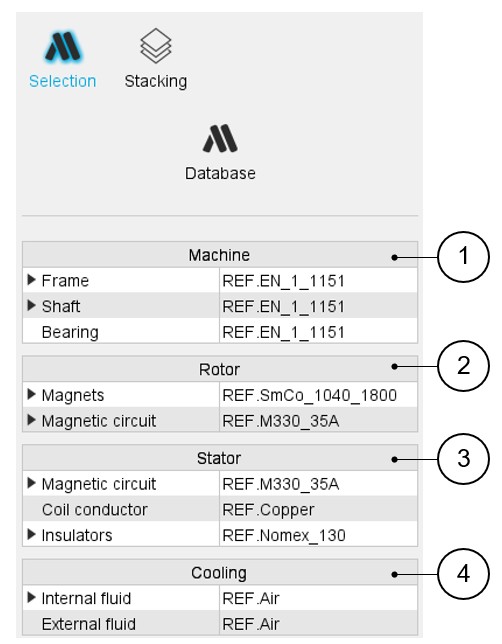
In the section “Selection”, several fields allow you to assign materials to every region of the machine.
 |
|
|---|---|
| 1 | Area to assign materials to machine regions (frame, shaft, bearings) |
| 2 | Area to assign materials to rotor regions (magnets, magnetic circuit) |
| 3 | Area to assign materials to Stator regions (magnetic circuit, coil conductor, insulators) |
| 4 | Area to assign materials to Cooling fluids (internal fluid, external fluid) |
How to assign materials?
 |
|
|---|---|
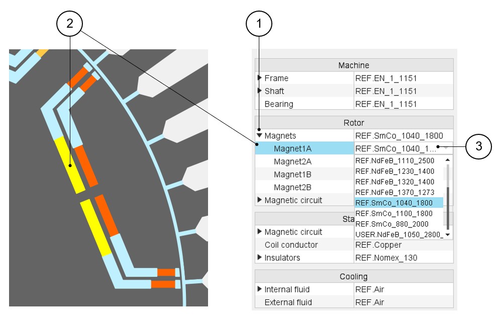
| 1 | Expand the dedicated section. In our example with magnets, several magnet materials can be assigned to the same rotor pole. Here four magnets are defined. Different magnet materials can be assigned to each of them. |
| 2 | By selecting a region name (Magnet1A, for example), the corresponding face region is highlighted. |
| 3 | Expand the material list to choose a magnet material for assigning to the selected magnet. |
Example for rotor lamination
 |
|
|---|---|
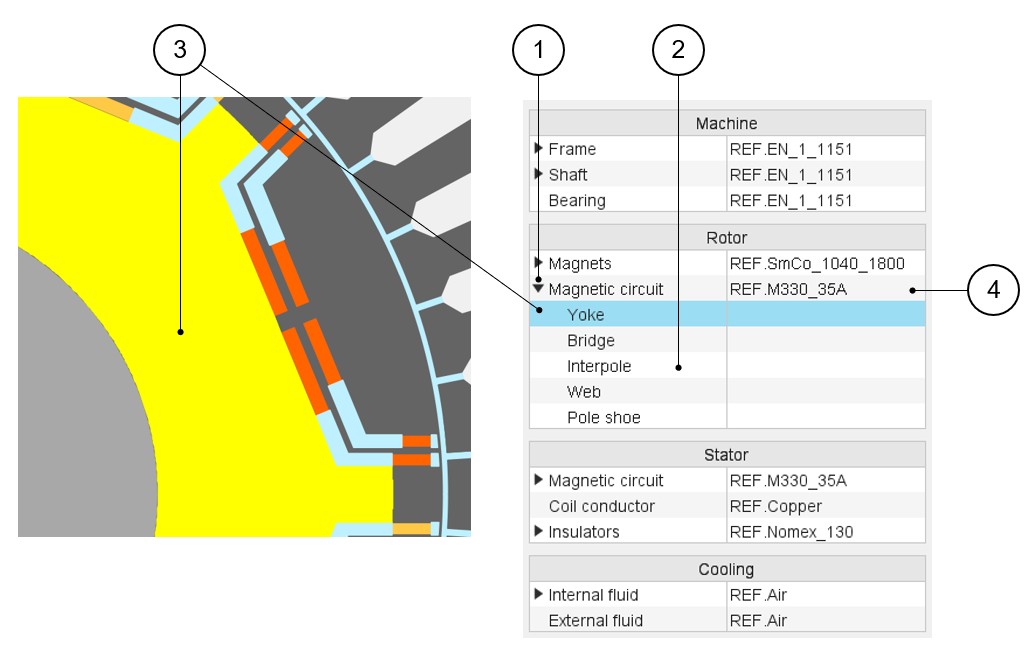
| 1 | Expand the section dedicated to the magnetic circuit. Different materials (Lamination type or Solid type) can be assigned to it. |
| 2 | The magnetic circuit can be subdivided into several parts. (Yoke, Bridge, Web etc.) |
| 3 | By selecting a region name (Yoke, for example), the corresponding face region is highlighted. |
| 4 | Expand the material list to choose a material to assign to the
magnetic circuit. Only one material can be assigned to the rotor magnetic circuit. In our example it is not possible to assign different materials to sub regions like Yoke and Web. |
Example for stator lamination
 |
|
|---|---|
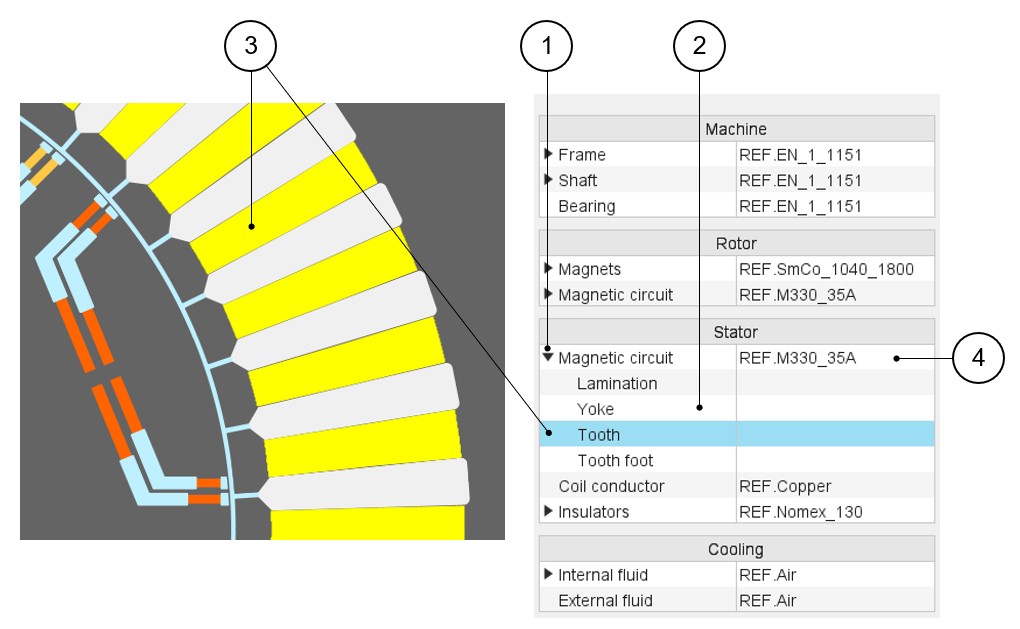
| 1 | Expand the section dedicated to the magnetic circuit. Different materials (Lamination type or Solid type) can be assigned to it. |
| 2 | The magnetic circuit of the stator can be subdivided into several parts (Yoke, Tooth, Tooth foot etc.). |
| 3 | By selecting a region name (Tooth, for example), the corresponding face region is highlighted. |
| 4 | Expand the material list to choose a material to assign to the
magnetic circuit. Only one material can be assigned to the stator magnetic circuit. In our example, it is not possible to assign different materials to sub regions like Yoke, Tooth and Tooth foot, for example. |
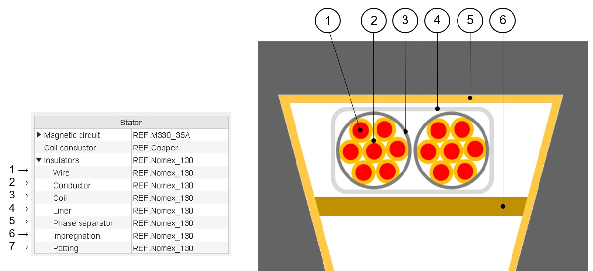
Materials for the winding
All the materials are selected in the material database.
Conductor materials are selected in the “Electrical Conductor” type material family.
Insulator materials are selected in the “Electrical Insulator” type material family.
Thicknesses of insulations are defined inside the winding settings panel – COIL tab.
Insulation materials are considered only if a corresponding thickness is defined.
 |
|
|---|---|
| 1 | Wire insulation |
| 2 | Conductor insulation |
| 3 | Coil insulation |
| 4 | Liner |
| 5 | Phase separator |
| 6 | Impregnation inside the slot |
| 7 | Material used for encapsulating the end-windings (potting) |
Materials datasheet
In the Materials datasheet, the parameters written in blue correspond to user input parameters and the parameters written in black correspond to data resulting from computations.