Design
 |
|
|---|---|
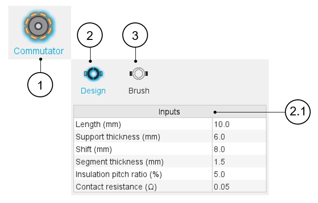
| 1 | Selection of the Rotor subset: Commutator panel (Click on the
icon Commutator) Selection of the Commutator panel (Click on the Commutator icon) Several sections allow defining all characteristics that deal with the commutator: Design and Brush. |
| 2 | Commutator design tab to establish global parameters, both geometrical and electrical |
| 2.1 | Commutator-Design input data to be defined (1) |
| 3 | Brush design tab to introduce the brush related parameters |
(1) Here is the list of the commutator design parameters:
- Length : Commutator axial length.
- Support thickness: Thickness of the not conducting material that is
supporting the commutator segments.
Since it has cylindrical form, it corresponds to its radius.
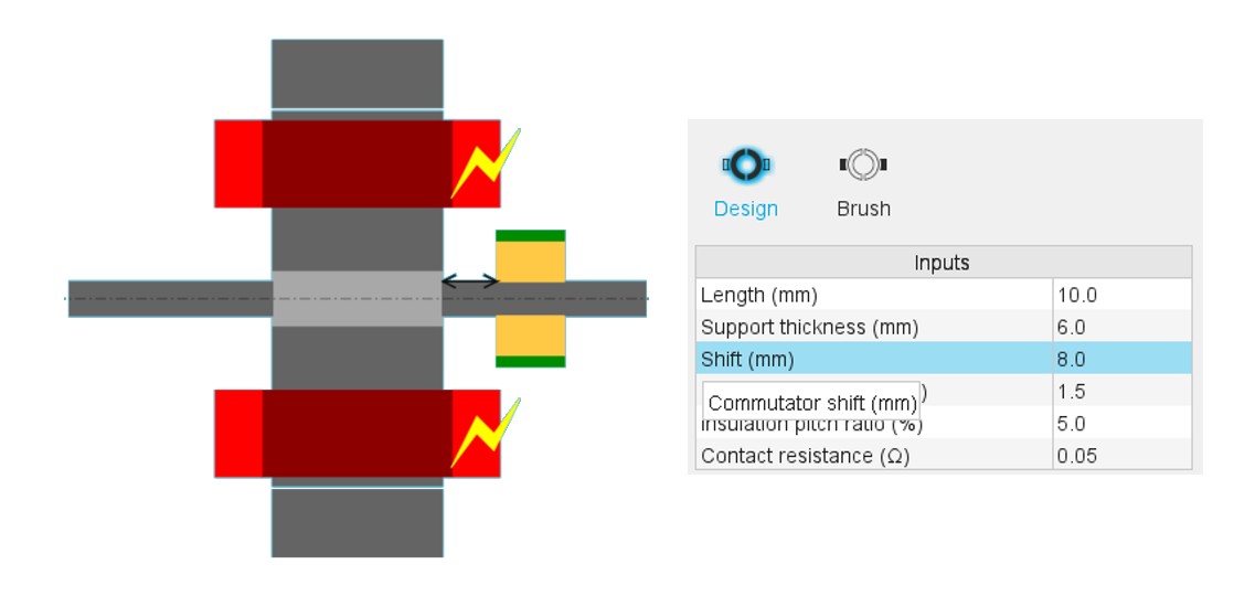
- Shift: Commutator shift
- Segmentation thickness: Thickness of the conductive commutator segments.
- Insulation pitch ratio: Angular ratio of the insulation between commutator segments
- Contact resistance: Contact resistance between the brushes and the commutator segments
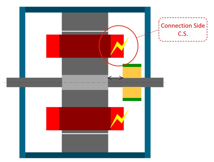
Note: By definition, the commutator is always placed in the
connection side (C.S.) which is identified by a yellow lighting.
Note: In the commutator datasheet, the parameters written in
blue correspond to user input parameters and the parameters written in black
correspond to data resulting from computations.
 |
|
|---|---|
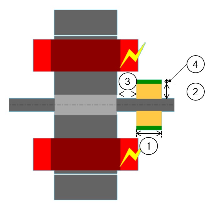
| 1 | Length |
| 2 | Support thickness |
| 3 | Shift |
| 4 | Segmentation thickness |