Brush
Overview
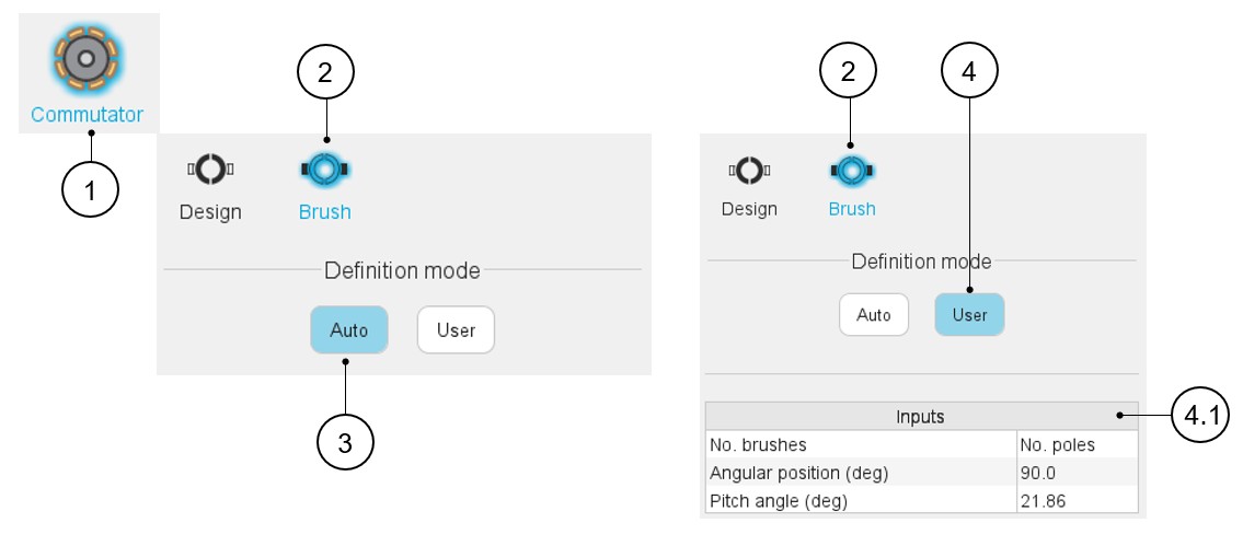
Two options are available in the commutator-brush definition mode:
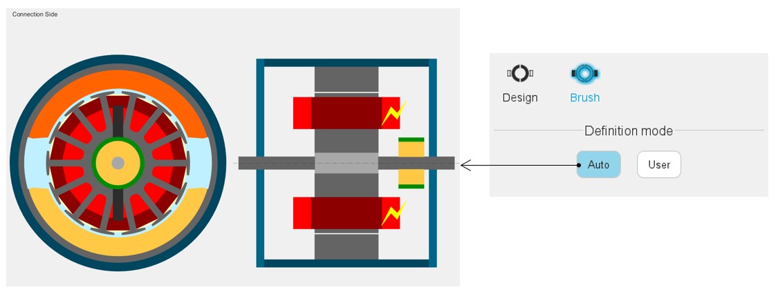
- Auto: Brushes dimensions and angular position are automatically calculated by FluxMotor to get the best fit with the defined winding (see below).
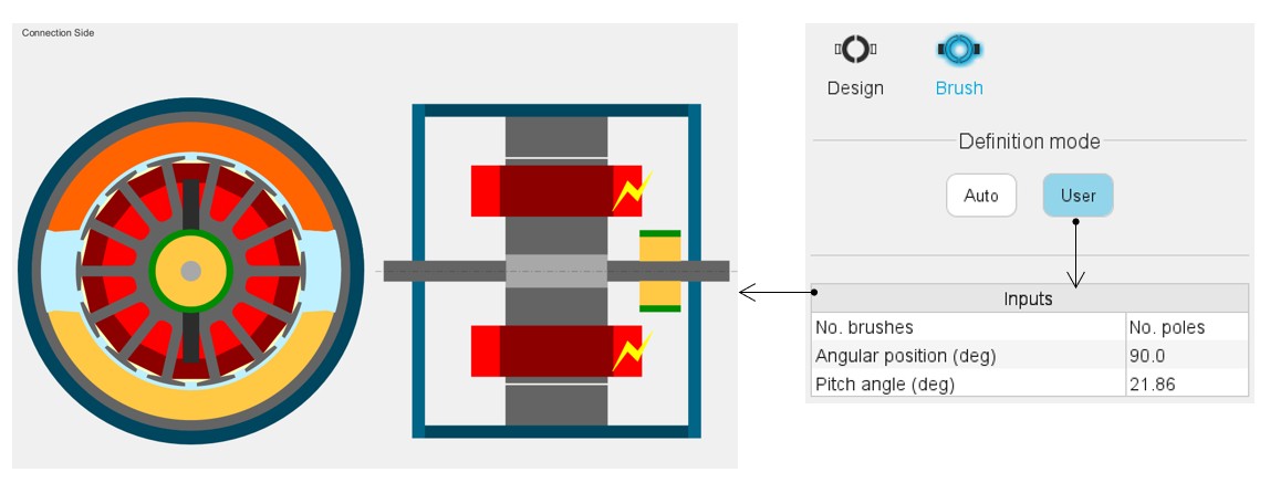
- User: Brushes dimensions and angular position are defined by the user.
 |
|
|---|---|
| 1 | Selection of the Rotor subset: Commutator panel (Click on the icon Commutator). |
| 2 | Brush design tab to introduce brush related parameters. |
| 3 | Auto mode: Brushes dimensions and angular position are automatically calculated by FluxMotor to get the best fit with the defined winding. |
| 4 | Brushes dimensions and angular position are defined by the user. |
| 4.1 | Commutator-brush input data to be defined. This is only available in user mode (1). |
(1) Here is the list and the description of the commutator brush parameters:
| Label | Tooltip, note | Default value (auto mode) |
|---|---|---|
| Nº of brushes | Number of brushes. Only unblocked for wave winding | Number of poles |
| Angular position | Angular position of the reference brush (polarity +) | Center of a north pole (for lap winding) Center of a south pole (for wave winding) |
| Pitch angle | Pitch angle of a brush | 0.85 times the segment commutator pitch for simplex winding (1.85 for duplex and 2.85 for triplex) |
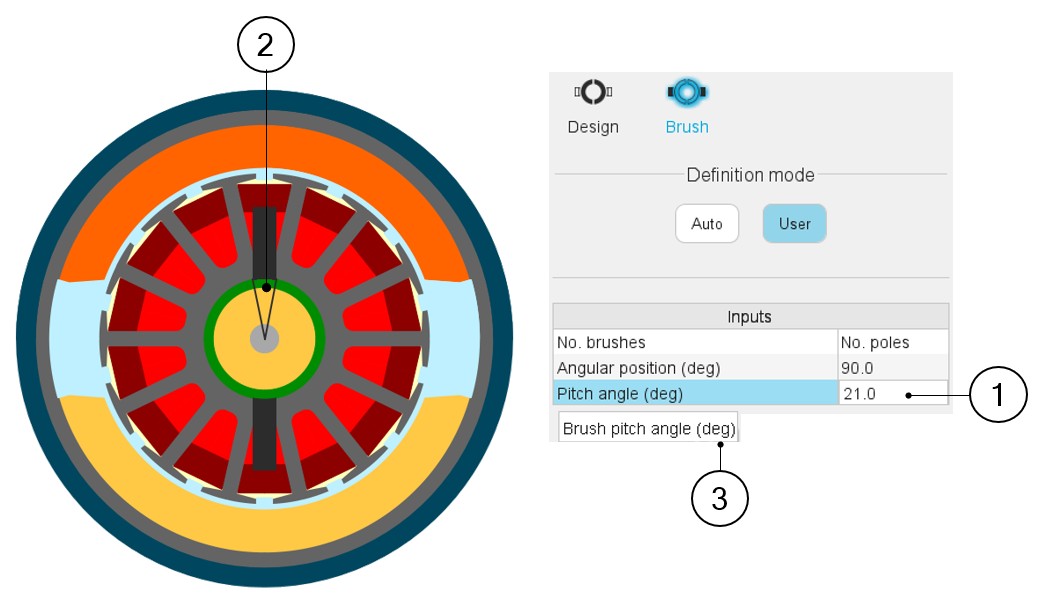
Illustrations of these parameters are shown below.
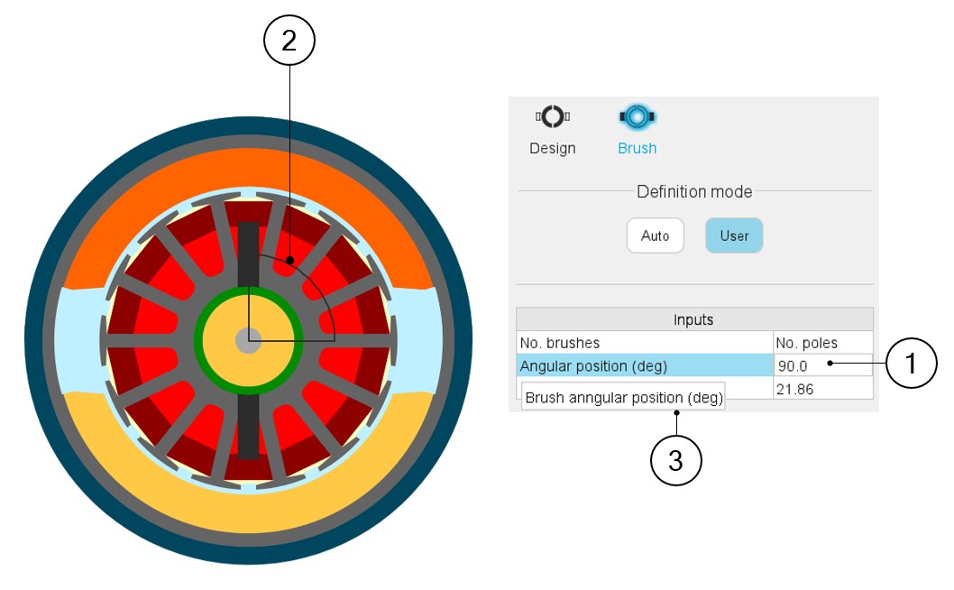 |
|
|---|---|
| 1 | Selecting a parameter highlights it. |
| 2 | Selecting a parameter label displays the corresponding angle on the picture. |
| 3 | Selecting a parameter displays the corresponding tooltip which provides additional information |
 |
|
|---|---|
| 1 | Selecting a parameter highlights it. |
| 2 | Selecting a parameter label displays the corresponding angle on the picture. |
| 3 | Selecting a parameter displays the corresponding tooltip which provides additional information |