Multiple Heights
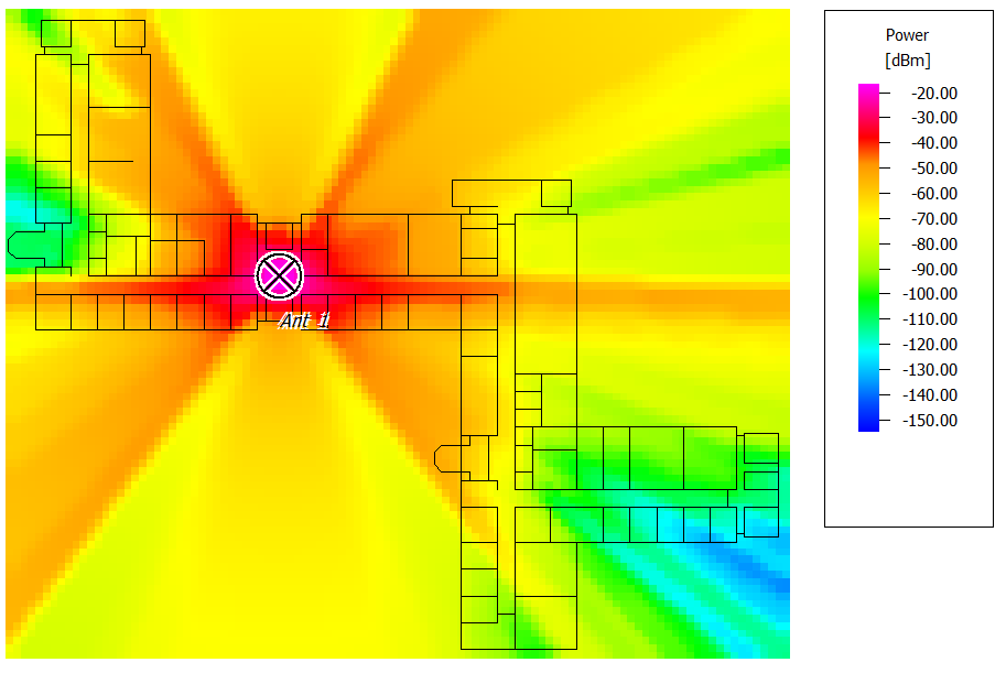
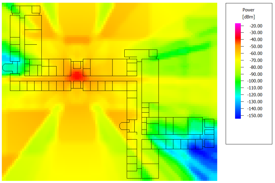
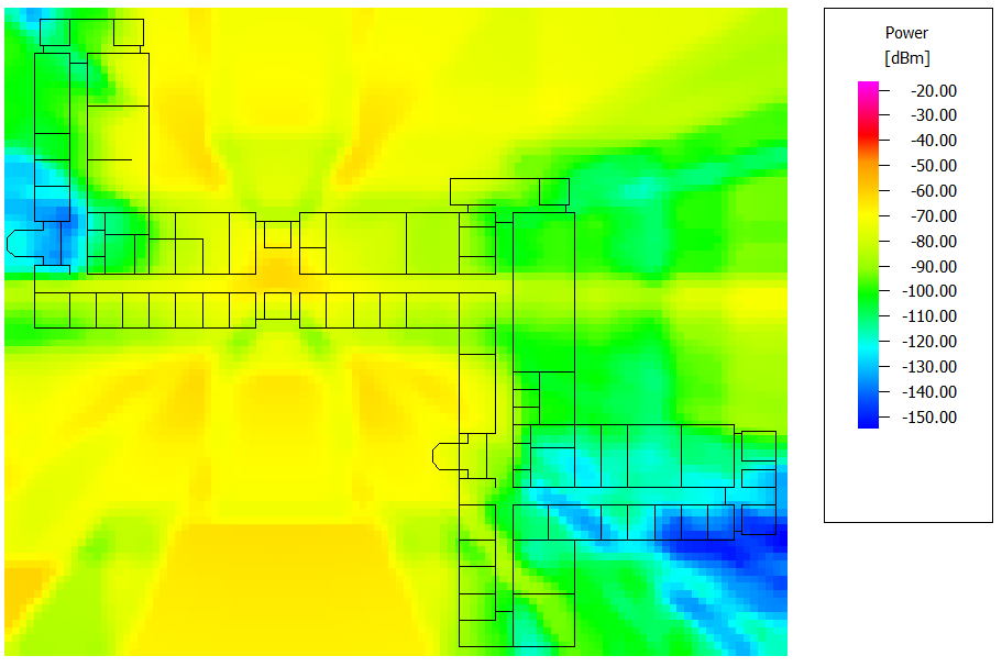
Compute path and transmission losses on three different prediction planes.
Model Type
The propagation project is for an indoor scenario for a large multi-floor building. The simulation is done for three different prediction planes.
Sites and Antennas
- Antenna 1 at Site 1 is located at a height of 2.5 m.
- Antenna 2 at Site 2 is located at a height of 6.2 m.
- Antenna 3 at Site 3 is located at a height of 9.9 m.
Computational Method
The computational method used is the multi-wall model (COST 231). The multi-wall model considers the basic path losses plus transmission losses for the walls and floors given a straight path between the transmitter and receiver. This model has a low dependency on the database accuracy, and because of this simple approach, very short computation time is required. Therefore no preprocessing of the building data is needed for the computation of the prediction. No settings need to be adapted for this prediction model.
Results
Propagation results show, at every location, the power received from each transmitting antenna individually. The results for antenna 1 are shown for three prediction planes of height 1.5 m, 5.2 m, and 8.9 m. The received power is highest on the floor where the antenna is located due to the absence of transmission loss through different floors.


