This section contains the tutorials for the following tools: Block JIG Generator, Compare GDSII, Gerber to PCB, Make
Board Paneling, Metal Mask Manager, Mounting Data Extractor, Mounting Emulator, Router-Machine JIG Generator, Solder
Quantity Calculator, Soldering Pallet, Test Point Location Generator, and Underfill.
Block JIG Generator is used for the purpose of stable supporting the bare PCB and evenly applying lead in the screen printer equipment
that prints the solder cream during the SMD process.
Make Board Paneling is a function to modify the data designed with a single sub board into an array type to use manufacturing related
features such as Metal Mask Manager, Mounting Emulator, Block JIG Generator, Router-Machine JIG Generator, and so on.
Use Metal Mask Manager to register standard metal mask database, manage metal mask changing history, and check differences between design
and standard metal mask.
PollEx Mounting Data Extractor extracts components and PCB information for chip mounter from PCB design data. It is included in the PollEx PCB Modeler.
The Mounting Emulator pre-verifies and corrects the mounting coordinate data by utilizing the 3D component package library (UPF Library)
information registered through UPE.
Solder Quantity Calculator is used to calculate the amount of lead used in PCB manufacturing in advance based on the design data imported to
PollEx PCB.
Underfill is a method of filling a thermo-hardening resin (epoxy) between the PCB top side and the bottom side of the chip
to produce sound mechanical and thermal properties, and to protect the package chips from physical or thermal shock
to ensure reliability.
This section contains the tutorials for the following tools: BOM, CAM, Component Arrangement Plan, CP, Golden Sample,
Logic, PCB, Redmark+, and Worksheet Planner.
This section contains the tutorials for the following tools: Block JIG Generator, Compare GDSII, Gerber to PCB, Make
Board Paneling, Metal Mask Manager, Mounting Data Extractor, Mounting Emulator, Router-Machine JIG Generator, Solder
Quantity Calculator, Soldering Pallet, Test Point Location Generator, and Underfill.
Solder Quantity Calculator is used to calculate the amount of lead used in PCB manufacturing in advance based on the design data imported to
PollEx PCB.
Solder Quantity Calculator is used to calculate the amount of lead used
in PCB manufacturing in advance based on the design data imported to PollEx PCB.
For the wave soldering, solder mask area is calculated to estimating the lead amount.
By using the solder mask information of the PCB design data, you can easily
calculate the area on the Solder Quantity Calculator. For the reflow
soldering, the lead amount can be calculated according to the area of the metal
mask, the thickness of the metal mask, and the material of the solder cream.
Launch PollEx PCB.
Open the design file.
From the menu bar, click File > Open and open the PollEx_New_Sample.pdbb
from
C:\Temp\Altair-PollEx\Manufacture\SolderQuantityCalculator.
Refer to the PCB for how
to use the PollEx PCB viewer.
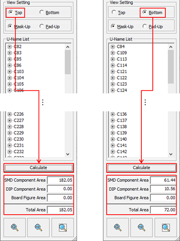
From the menu bar, click Manufacture > Solder Quantity Calculator > Solder Mask.
In the View Setting section, select Top or
Bottom and click Calculate to
calculate the Solder Mask area.
Figure 1.
You can check the solder mask area per SMD, DIP (Through Hole), and board
figure.
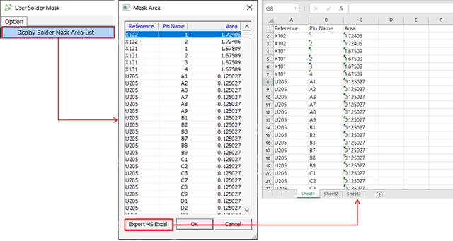
Check the Solder Mask area per each component pin.
From the menu bar, click Option > Display Solder Mask Area List.
Figure 2.
Click Export MS Excel to export the solder mask
area per each component pin as an Excel document.
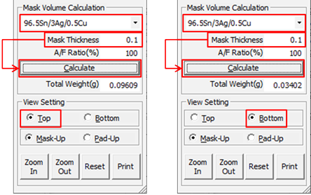
From the menu bar, click Manufacture > Solder Quantity Calculator > Metal Mask to run Metal Mask.
Calculate the Metal Mask Area.
Figure 3.
In the View Setting section, select Top or
Bottom.
In the Mask Volume Calculation section, select the material of the
solder cream from the drop-down menu and enter Mask
Thickness.
Click Calculate to calculate the lead
amount.
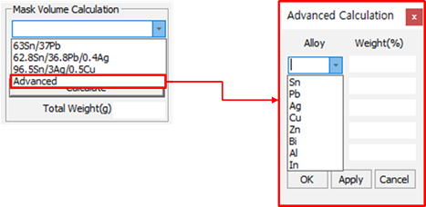
Select Advanced when selecting a solder cream
material to set the composition ratio of the material. Figure 4.
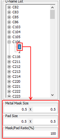
Select a component pin to check the pad size and metal mask size.
Figure 5.
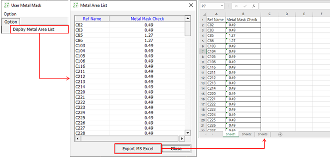
Check the Metal Mask area per a component.
From the menu bar, click Option > Display Metal Mask Area List.
Figure 6.
Click Export MS Excel to export the metal mask
area per a component as an Excel document.