Make Board Paneling Tutorial
Make Board Paneling is a function to modify the data designed with a single sub board into an array type to use manufacturing related features such as Metal Mask Manager, Mounting Emulator, Block JIG Generator, Router-Machine JIG Generator, and so on.
Make Board Paneling using PDBB
-
Create array number four.

Figure 1.
Figure 2.
Figure 3. -
Create Panel outline.
In the Define Panel outline section, you can define the Panel Board outline.

Figure 4.
Make Board Paneling using Gerber Data
-
Import Gerber data.
When the Metal Mask Gerber of the panel board is prepared, the sub-boards can be automatically calculated by selecting the component pad of the design data and the pad object of the Gerber data.
-
In the Import from Gerber (RS-274D/RS-274X)
dialog, click
 .
.
-
From the tool bar, click
 to
disable routing data.
to
disable routing data.
-
In the Import from Gerber (RS-274D/RS-274X)
dialog, click
-
From the menu bar, click .
The Make Board Paneling dialog opens. The design file is saved as a *.pdbb file. If the file is not saved, the Make Board Paneling cannot be used.

Figure 5. -
Create Array List by selecting CAD and Gerber data.
- In the Paneling Object Definition section of the Make Board Paneling dialog, enable the following checkboxes: Route, Board Figure, and Board Outline.
- In the Placement section, enable the Object Select checkbox and select CAD Object.
- Select the Pad to be used as the reference from the CAD data.

Figure 6. -
Select pad based on Gerber data.
-
Click Add Board to enter the first array
information in the Array list.
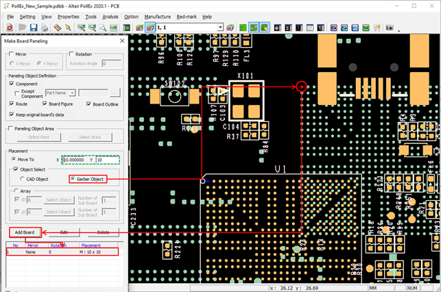
Figure 7. -
Click Add Board to enter the second array
information in the Array list.

Figure 8. -
Click Apply.
The original data is copied and arranged as registered in the Array list.

Figure 9.
-
Click Add Board to enter the first array
information in the Array list.
-
Create Panel outline.
Use the Get Panel Outline from Gerber option to define the Panel Outline.
-
Click Get Panel Outline from Gerber.

Figure 10.The Extract Board Outline dialog opens. -
Enable the Certain Width checkbox and enter
0.2.

Figure 11. -
Click ALL.
All lines with the same width as the previously selected line are automatically selected and displayed in purple in the Gerber data.

Figure 12. -
Click Close in the Make Board
Paneling dialog.

Figure 13.
-
Click Get Panel Outline from Gerber.