This tutorial is primarily designed to help you get started start with the PollExCompare GDSII tool.
It is not intended to be a complete reference guide for all available functions, but
provides you with an overview of key concepts. Understanding these concepts allows
you to learn how to use this tool efficiently with the help of the documentation, by
pressing F1 within the PollEx
application.
Launch PollEx PCB.
From the menu bar, click File > Open and open the
PollEx_MFG_Sample_T4_r<revision
number>.pdbb file from
C:\ProgramData\altair\PollEx\<version>\Examples\MFG.
Export to GDSII.
From the menu bar, click File > Export to > GDSII.
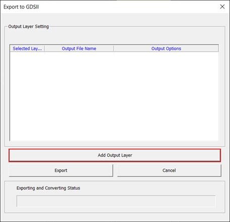
The GDSII Output Setting dialog opens.
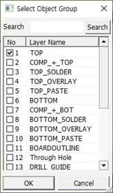
In the GDSII Output Setting dialog, click
Add Output Layer to select the layer
combination to be output.
Figure 1.
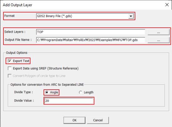
Set the layers and condition to be output and click OK.
Figure 2.
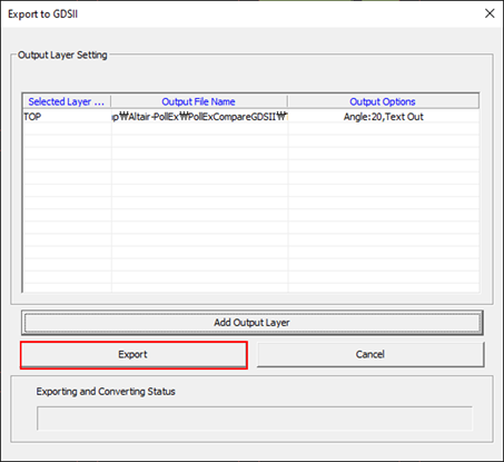
Click Export.
Figure 3.
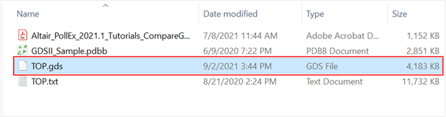
The TOP.gds file is exported to the design
folder. Figure 4.
Compare GDSII.
The Compare GDSII function verifies the consistency between the data in the
specific layer of PDBB and the GDSII file.
From the menu bar, select Tools > Compare GDSII.
The Compare PDB and GDS2 dialog
opens.
For Select PDB Layer, select TOP.
Figure 5.
For Select GDSII file, select the GDSII file
(*.txt).
Click OK.
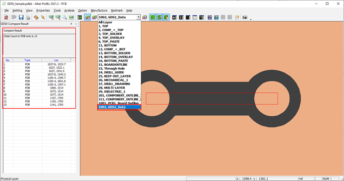
Compared result.
After the comparison, the result window appears on the left of PollEx PCB
Modeler as shown in Figure 7.Figure 6.
When the comparison function is performed, a layer for displaying GDSII
data is added, and GDSII data is input to the corresponding layer. Figure 7.