The Mounting Emulator pre-verifies and corrects the mounting
coordinate data by utilizing the 3D component package library (UPF Library) information
registered through UPE.
It minimizes the time spent on test production and discarded parts, thereby saving
the cost of manufacturing and mass production.
Launch PollEx PCB and open layout design file.
Click PollExPCB from the PollEx Launcher.
Click File > Open and open
PollEx_MFG_Sample_T1_r<revision
number>.pdbb from
C:\ProgramData\altair\PollEx\<version>\Examples\MFG.
Refer to the PCB for how
to use the PollEx PCB viewer.
Save as Project.
PollEx PCB operates on a design project database
which contains entire data of a PCB design including the materials, parts,
physical layout, analysis models and analysis result data. With the use of
unified design project database, this application can be commonly used by
multiple engineering disciplines.
From the menu bar, click File > Save as Project to create a new PollEx project directory from
scratch.
The sample PCB design name is displayed as the New project name
in the Save As Project dialog.
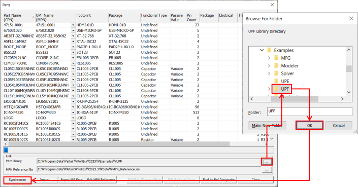
Link Unified Part Libraries.
From the menu bar, click Properties > Parts.
Click to specify the Part Library
Directory.
Select the UPF folder from
C:\ProgramData\altair\PollEx\<version>\Examples\UPF
and click Synchronize.
Figure 1.
You can check the linked data in the package, electrical and
thermal columns for 3D package shape for SI and Thermal analysis.
Click Close.
Open the Mounting Emulator and verify mounting data.
From the menu bar, click Manufacture > Mounting Emulator.
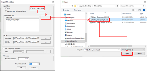
From the menu bar, click File > Import.
Figure 2.
The Import Mount Data dialog
opens.
In the Import Mount Data dialog, select
BOM + Mount Data.
Click and select the
PollEx_New_Sample.crb found here:
C:\ProgramData\altair\PollEx\<version>\Examples\MFG\MountingEmulator\MountData.
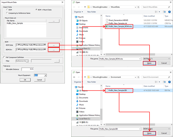
Figure 3.
Click and select the
PollEx_New_Sample_BOM.xlsx file found here:
C:\ProgramData\altair\PollEx\<version>\Examples\MFG\MountingEmulator\MountData.
Click and select the
PollEx_New_Sample.EBI found here:
C:\ProgramData\altair\PollEx\<version>\Examples\MFG\MountingEmulator\Environment.
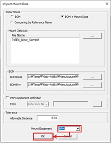
For Mount Equipment, select NPM and click
OK.
Figure 4.
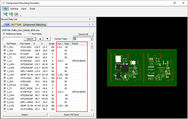
Review the results.
Figure 5.
After verification the results are listed.
Location Difference: The location of the part is shifted as much as the
indicated coordinates.
Angle Difference: The angle of the part is shifted as much as the
indicated value.
Result: Shows the comment for the result.
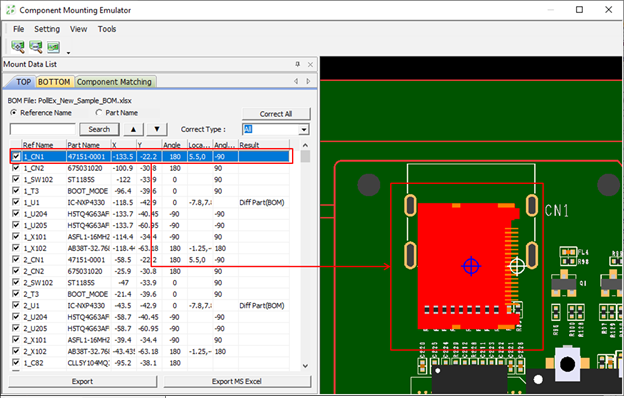
Figure 6.
Select a part from the list.
The selected part displays on the right side.
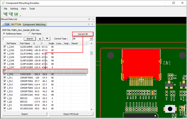
Correct the Mounting Data in the result.
Figure 7.
Click Correct All.
The mounting information of all parts with different mounting
positions and angles are corrected. Parts that reflect the corrections
are shaded gray.
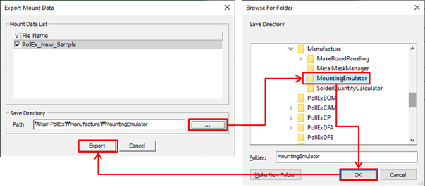
Export Mounting Data.
From the menu bar, click File > Export > To Mount Data > Normal.
Select the mounting data that has been calibrated in the
Export Mount Data dialog.
Figure 8.
Click in the Save Directory, define the file path
to export, and click Export.
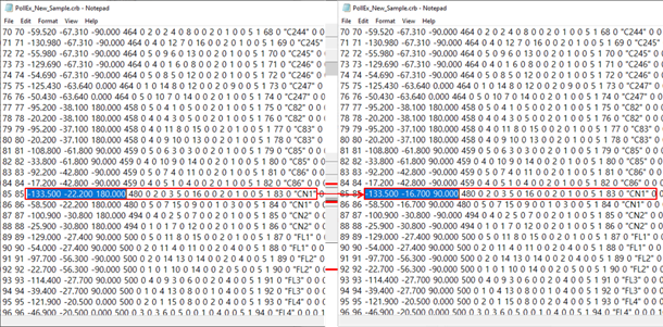
Figure 9.
In the exported file, you can check the corrected coordinate and
angle in the Mounting Emulator.
 to specify the Part Library
Directory.
to specify the Part Library
Directory.