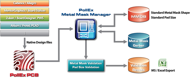
Use Metal Mask Manager to register standard metal mask
database, manage metal mask changing history, and check differences between design and
standard metal mask.
You can change a designs metal mask according to standard metal mask. Depending on
manufacturing process and products, you can manage several different metal mask
databases. You can import standard metal mask after reading design and check
different metal masks among design, Gerber, and standard metal mask.
Figure 1.
Launch PollEx PCB and open layout design file.
From the PollEx Launcher, click
PollExPCB.
Click File > Open and open
C:\ProgramData\altair\PollEx\<version>\Examples\MFG\PollEx_MFG_Sample_T1_r1.0.pdbb.
Refer to the PCB for how to use
the PollEx PCB viewer.
Run Metal Mask Manager.
From the menu bar, click Manufacture > Metal Mask Manager.
Refer to Metal Mask Manager
for more detailed information on how to use.
Create the Metal Mask DB.
If the created Package Metal Mask DB (*.mmdb) file is exited, you can use this file instead.
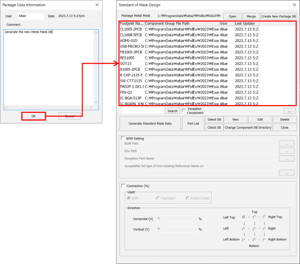
From the menu bar, click Tools > Standard of Mask Design.
In the Standard of Mask Design dialog, click
Create New Package DB.
Enter StandardMetalMaskDB.mmdb for the file name
and save the file in
C:\ProgramData\altair\PollEx\<version>\Examples\MFG\MetalMaskManager.
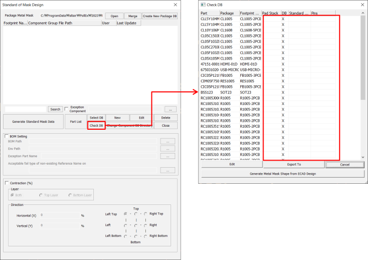
Figure 2.
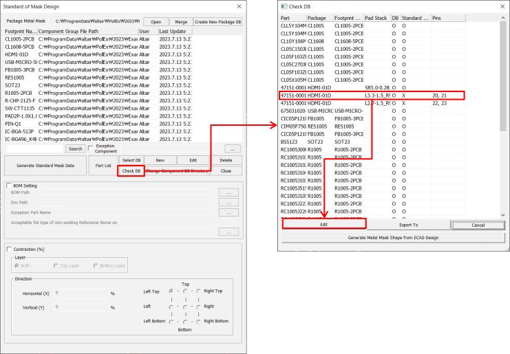
You can click Check DB to check if the
padstack and DB for each component placed in the design data are
registered in the currently opened Package Metal Mask DB
(*.mmdb) file.
Metal Mask Manager provides the function to automatically register the
metal mask shape of the components placed in the CAD data in the Package
Metal Mask DB (*.mmdb).
In the Check DB dialog, click Generate
Metal Mask Shape from ECAD Design.
Click in the Component DB Path category, and set
the directory as:
C:\ProgramData\altair\PollEx\<version>\Examples\MFG\MetalMaskManager\ComponentDB.
If the folder does not exist, create it first.
Click Generate.
Figure 3.
Enter a comment in the Package Data Information
dialog for managing the history of the metal mask DB modification.
Click OK to register
the components in the Package Metal Mask DB (*.mmdb).
Edit the Metal Mask DB.
Figure 4.
In the Standard of Mask Design dialog, click
Check DB to check that the component DB and
the standard metal mask shape are registered.
For the part name 47151-0001, pins from 20 to 23 are not registered
and the corresponding pad stack names are L3.3-1.5_R90_T, and
L2.7-1.5_R90_T respectively.
Click Edit to edit the metal mask of the
selected part.
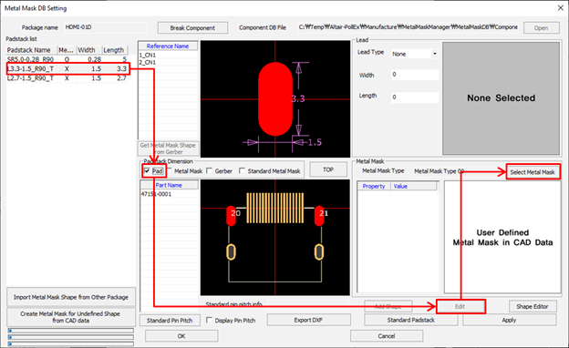
Figure 5.
Select L3.3-1.5_R90_T from the Padstack
list.
Enable the Pad checkbox in the Padstack
Dimension section to check the pad size.
Click Edit.
Click Select Metal Mask.
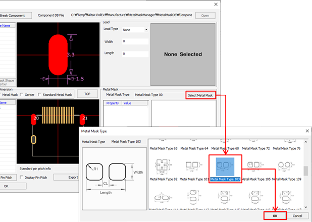
Figure 6.
In the Metal Mask Type dialog, select the
Metal Mask Type 103 and click
OK.
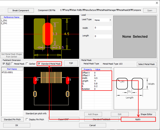
Figure 7.
In the Metal Mask section, enter the following values for the metal
mask size information and click Apply.
Offset X/Y = 0
Width = 4.5
Length = 4
CL = 0.8
R = 0.2
Rotation = 0
Enable the Standard Metal Mask checkbox to check
the size of the created metal mask shape.
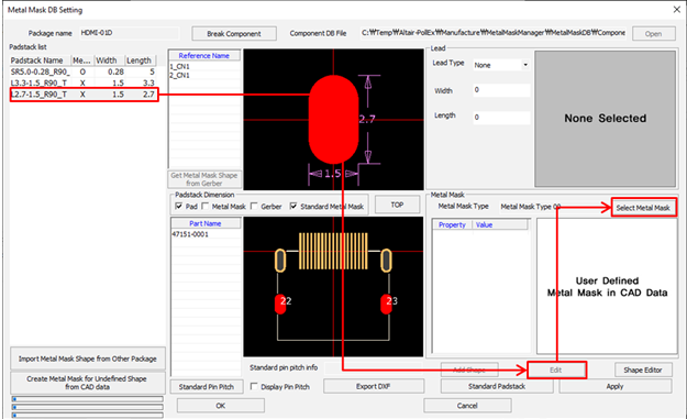
Figure 8.
Select L2.7-1.5_R90_T from the Padstack
list.
Click Edit and Select Metal
Mask.
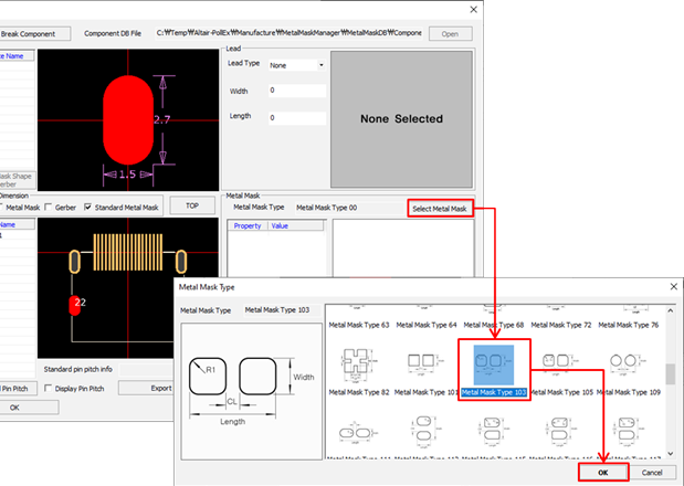
Figure 9.
In the Metal Mask Type dialog, select
Metal Mask Type 103 and click
OK.
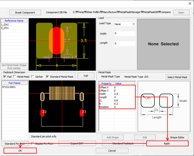
Figure 10.
In the Metal Mask section, enter the following values for the metal
mask size information.
Offset X/Y = 0
Width = 3.5
Length = 4
CL = 0.8
R = 0.2
Rotation = 0
Click Apply to apply
the entered values.
Click OK to close the
Metal Mask DB Setting dialog.
Enter a comment in the Package Data Information
dialog and click OK.
The Modified part is displayed in blue.
Click Close to close the Standard of
Mask Design dialog.
Apply Package Metal Mask DB.
From the menu bar, click Tools > Standard of Mask Design.
Click Open to load the
StandardMetalMaskDB.mmdb file from
C:\ProgramData\altair\PollEx\<version>\Examples\MFG\MetalMaskManager.
Create Metal Mask.
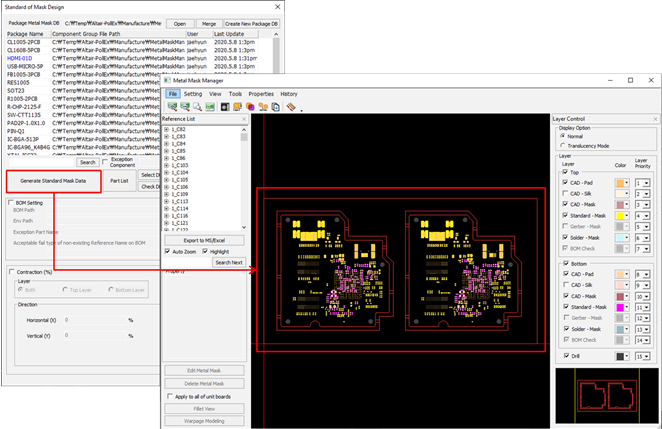
Figure 11.
Click Generate Standard Mask Data.
The metal mask shape of each part registered in the Package Metal Mask
DB (*.mmdb) is reflected to
the design data.
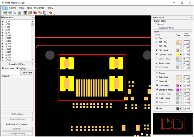
Figure 12.
The modified metal mask shape is reflected in the image
above.
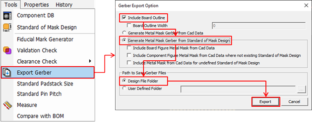
Export to Metal Mask Gerber.
From the menu bar, click Tools > Export Gerber.
Figure 13.
In the Gerber Export Option dialog, enable the
Include Board Outline checkbox.
Select Generate Metal Mask Gerber from Standard of Mask
Design.
Select Design File Folder in the Path to Save
Gerber Files section.
 in the Component DB Path category, and set
the directory as:
C:\ProgramData\altair\PollEx\<version>\Examples\MFG\MetalMaskManager\ComponentDB.
If the folder does not exist, create it first.
in the Component DB Path category, and set
the directory as:
C:\ProgramData\altair\PollEx\<version>\Examples\MFG\MetalMaskManager\ComponentDB.
If the folder does not exist, create it first.