Block JIG Generator Tutorial
Block JIG Generator is used for the purpose of stable supporting the bare PCB and evenly applying lead in the screen printer equipment that prints the solder cream during the SMD process.
Block JIG Generator provides to quickly generate design drawing for manufacturing JIG using PCB design data and panel PCB Gerber of array board.
- Launch PollEx PCB.
- From the menu bar, click and open the PollEx_MFG_Sample_T1_r<revision number>.pdbb file from C:\ProgramData\altair\PollEx\<version>\Examples\MFG.
-
Import Gerber data.
-
From the Gerber (RS-274D/RS-274X) dialog, click
 .
.
-
From the Gerber (RS-274D/RS-274X) dialog, click
- From the menu bar, click .
-
Create Base Line.
-
In the Base Line section, select Top-Metal.phd
for Select Gerber Layer.
Figure 1. 
-
Select Top for Select Top Component.
Define the top component because the top surface between the PCB design data and the manufacturing process may be different.
Figure 2. 
-
Click Recognize Bridge.
The line corresponding to the bridge is automatically searched. The searched bridge lines are displayed in white.
Figure 3. 
-
Click Recognize Board Outline.
The board outline is automatically recognized from the Gerber data.
Figure 4. 
-
Click Select Board Outline.
The selected unit PCB outline is highlighted in red which is the basis for creating the base line.
Figure 5. 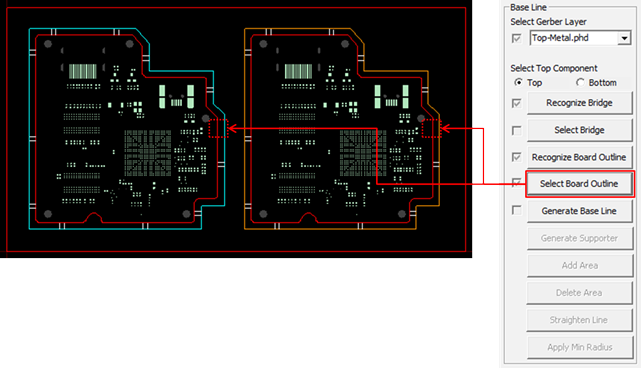
-
Click Generator Base Line.
The generated Base Line is displayed in purple.
Figure 6. 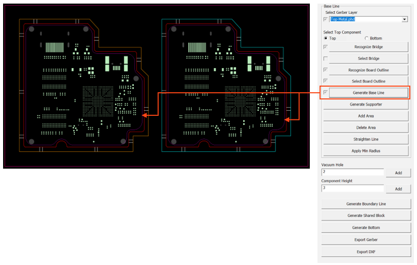
-
In the Base Line section, select Top-Metal.phd
for Select Gerber Layer.
-
Edit the Base Line.
-
Click the start and end points where you would like to add the Base
Line.
Figure 7. 
-
Right-click and select Done from the context menu.
The selected area is added to the Base Line.
Figure 8. 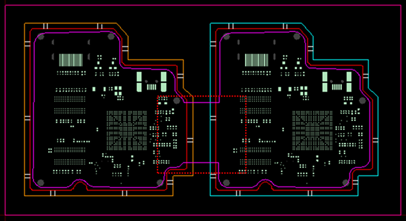
-
Click the start and end points where you would like to add the Base
Line.
-
Delete an area.
-
Click the start and end points where you would like to delete areas of
the Base Line.
Figure 9. 
-
Click the start and end points where you would like to delete areas of
the Base Line.
-
Straighten Line.
-
Click the two lines that are to be connected as a straight line.
Figure 10. 
-
Right-click and select Done from the context menu.
The selected area is changed to a straight line.
Figure 11. 
-
Click the two lines that are to be connected as a straight line.
-
Click Apply Min Radius to round the corners.
Figure 12. 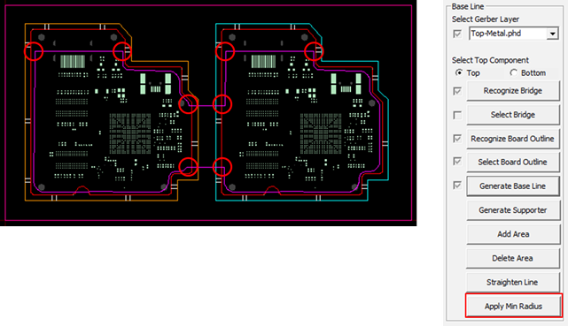
-
Click Generate Boundary Line.
The boundary line of the block JIG is generated and is displayed in yellow.
Figure 13. 
-
Click Generate Shared Block.
The shared block JIG line is generated is displayed in blue.
Figure 14. 
-
Click Generate Bottom.
The bottom line of the block JIG is generated and is displayed in blue.
Figure 15. 
-
Export JIG Data.
-
Click Export Gerber and specify the path to save
the data.
Figure 16. 
-
Click Export DXF and specify the path to save
the data.
Figure 17. 
-
Click Export Gerber and specify the path to save
the data.