Underfill is a method of filling a thermo-hardening resin
(epoxy) between the PCB top side and the bottom side of the chip to produce sound mechanical
and thermal properties, and to protect the package chips from physical or thermal shock to
ensure reliability.
Underfill is widely used for portable devices which receive
a lot of physical shock or for high-speed communication devices which receive a lot
of thermal shock. In the underfill process, the movement path of the nozzle and
applied amount of the thermo-hardening resin can be set to the bottom side of the
part through the underfill dispenser equipment. Using the Underfill
Editor and PCB design data, you can easily
produce the coordinate data of the nozzle movement path from the underfill
equipment.
Launch PollEx PCB.
From the menu bar, click File > Open and open the
PollEx_MFG_Sample_T1_r<revision
number>.pdbb file from
C:\ProgramData\altair\PollEx\<version>\Examples\MFG.
From the menu bar, click Manufacture > Underfill.
The Underfill dialog opens.
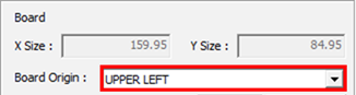
Define General settings.
From the General tab of the Underfill dialog,
select UPPER LEFT for Board Origin.
Figure 1.
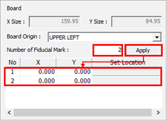
For Number of Fiducial Mark, enter 2 and click
Apply.
Figure 2.
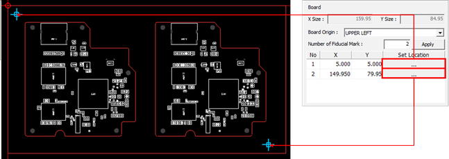
Click Set Location.
Click the location of the fiducial mark.
The X/Y coordinates are entered.Figure 3.
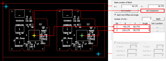
Click Set Component and select the U1 component
from the PCB data.
Figure 4. The center coordinate of the selected component is set as the base
location and the same part coordinates of each unit PCB are
automatically registered.
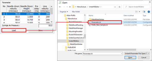
Click Load and select the
Parameter.ini file from
C:\ProgramData\altair\PollEx\<version>\Examples\MFG\Underfill.
Figure 5.
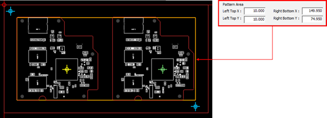
Set the area where the nozzle movement pattern for the underfill
application is drawn.
Figure 6.
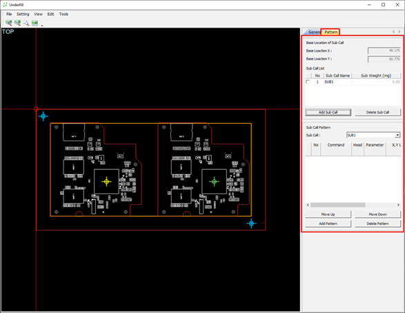
Define Pattern settings.
Figure 7.
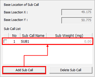
In the Pattern tab, click Add Sub Call to
register new sub call.
Figure 8. When applying multiple times, multiple sub calls can be
registered.
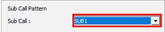
For Sub Call, select SUB1.
Figure 9.
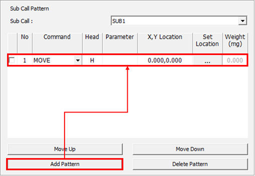
Click Add Pattern to create a new pattern.
Figure 10.
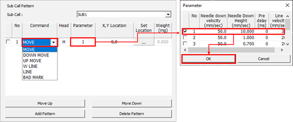
For Command, select Move.
Double-click the Parameter column.
The Parameter dialog opens.
In the Parameter dialog, enable the checkbox for
the first parameter and click OK.
Figure 11.
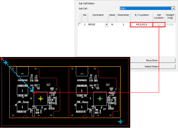
Click in the Set Location column and click the
location where the nozzle will move on the work screen.
Double-click the X,Y Location column to edit the
coordinates.
The nozzle of the underfill dispenser will move from (0,0) to (42.0,
-42.0). The moving speed and the height of the nozzle depend on the
value of the first parameter selected.Figure 12.
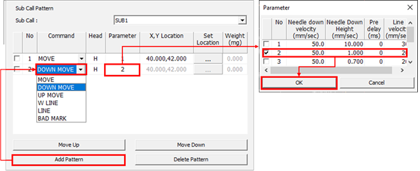
Click Add Pattern.
For Command, select DOWN MOVE and select the
parameter number two.
Double-click the Parameter column.
The Parameter dialog opens.
In the Parameter dialog, enable the checkbox for
the second parameter and click OK.
The nozzle of the underfill dispenser moves down to the height
set by the selected second parameter.Figure 13.
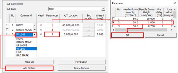
Click Add Pattern.
For Command, select W Line.
Double-click the Parameter column.
The Parameter dialog opens.
In the Parameter dialog, enable the checkbox for
the second parameter and click OK.
Figure 14.
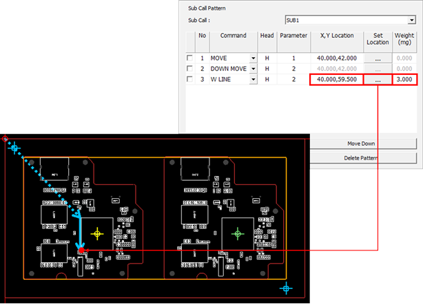
Click in the Set Location
column and set the position to move the nozzle on the work screen.
For Weight (mg), enter 3.
The nozzle of the underfill dispenser moves from (40.0,42.0) to
(40.0,59.5) and applies 3mg of the underfill solution. The moving speed
and height of the nozzle depend on the value of the second
parameter.Figure 15.
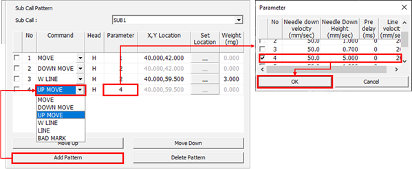
Click Add Pattern.
For Command, select UP MOVE.
Double-click the Parameter column.
The Parameter dialog opens.
In the Parameter dialog, enable the checkbox for
the fourth parameter and click OK.
The underfill dispenser nozzle moves up to the height set by the
fourth parameter.Figure 16.
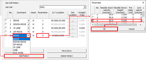
Click Add Pattern.
For Command, select MOVE.
Double-click the Parameter column.
The Parameter dialog opens.
In the Parameter dialog, enable the checkbox for
the fourth parameter and click OK.
Figure 17.
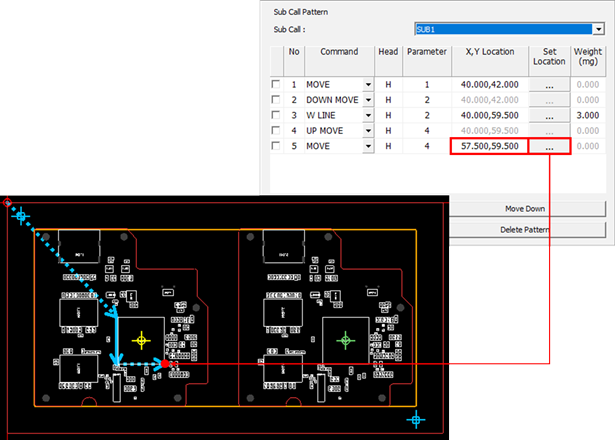
Click in the Set Location
column and set the location where the nozzle will move on the work
screen.
Figure 18.
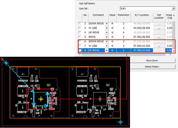
Repeat steps 5.i – 5.aa to complete the pattern as shown below.
Figure 19.
From the menu bar, click File > Save As.
Save Underfill Application Pattern data as a *.ini
file.
 in the Set Location column and click the
location where the nozzle will move on the work screen.
in the Set Location column and click the
location where the nozzle will move on the work screen.