Network Analysis Dialog Parameters
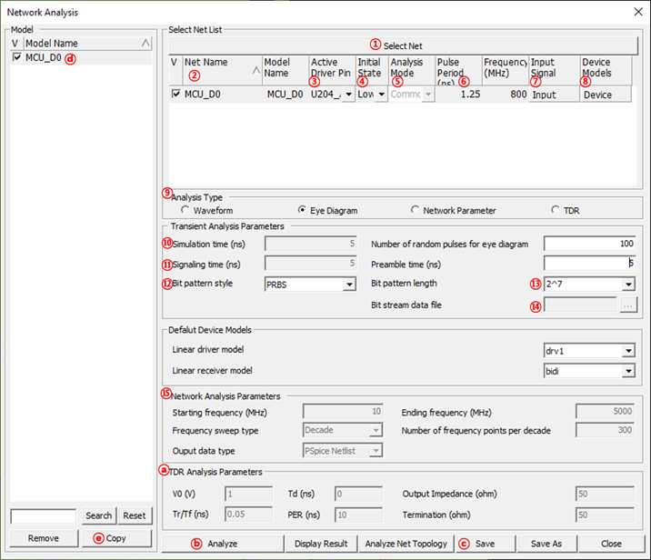
Figure 1.
- Select Net: Net for analysis can be selected over Select Net dialog.
- Net Name: All selected net names will be listed.
- Active Driver: You can specify the active driver pin among the connected pin to this net. The other pins will be assigned as receiver pin(s) automatically.
- Initial State: You can specify the initial value of input waveform.
- Analysis Mode: You can select the signal to assert the mode of the differential pair net. (Differential Mode/Common Mode)
- Pulse Period/Frequency: you can adjust the driver’s operating frequency/speed by changing this value.
- Input Signal: you can change the detailed parameters which can specify the
actual shape of the input signal, for example: TD (Time Delay), TR (Rise
Time), TR (Fall Time) and PW (Pulse Width).
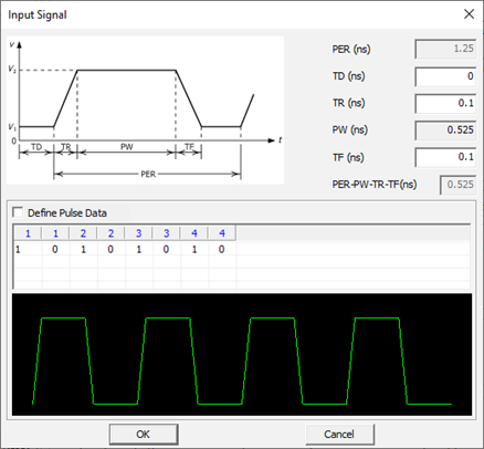
Figure 2. - Device Models: for the selected active driver, actual driver model can be
selectable among many different models in IBIS or Linear device model types.
You can use one of available models considering the output impedance,
driving capability measured by output current level and operating
frequencies. These driver’s characteristics lead huge impact on the
simulated waveforms.
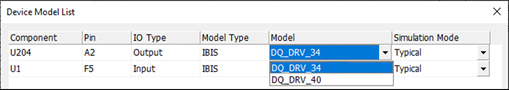
Figure 3. - Analysis Type: click the desired analysis type. Editable setting parameters will be shown.
- Simulation time: End time of the SPICE transient analysis.
- Signaling time: Input Signal having pulse period (2ns) will be excited to the net until the time assigned here.
- Bit pattern style: when you select the Eye diagram analysis, you can change
the random bit generation algorithms among Random, ABS, PRBS, Periodic and
Bit stream data file. By using the Bit stream data file menu, you can import
the file where the arbitrary bit stream is defined.
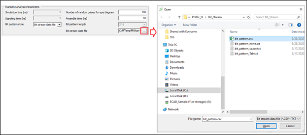
Figure 4. - Bit pattern length: total number of random bits will be applied to the net.
- Bit stream data file: assign bit stream data file, you can use CSV and TXT
format files. The separator between bits in the text format file is None,
Space, and Tab. The separator between bits in the CSV format file is ",".
See sample .csv file in Figure 5.
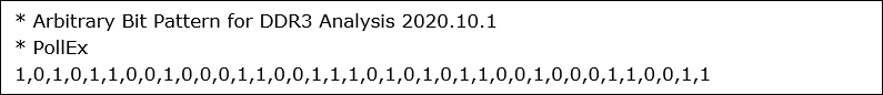
Figure 5. - Network Analysis Parameters: specify the start and end frequencies, total
number of frequency points and the method of sweeping the frequency points.
- Linear: Network parameter will be solved for 300 frequency points
between 10 MHz ~ 5000 MHz.
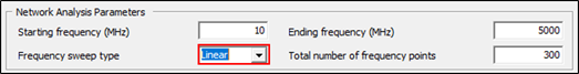
Figure 6. - Decade: Network parameter will be solved for 300 frequency points,
50 points from 1MHz ~ 10MHz, 10MHz~100MHz and 100MHz~1000MHz
respectively.
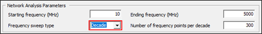
Figure 7.
- TDR Analysis Parameters: the parameters for
TDR analysis are as follows.
- V0: square wave voltage output from the driver stage.
- Tr/Tf(ns): rising/Falling time of square wave output from Driver.
- Td(ns): the initial delay time of the square wave output from the driver stage.
- PER(ns): the period of the square wave output from the driver stage.
- Output Impedance(ohm): the output impedance of the driver.
- Termination (ohm): the termination Impedance.
- Analyze: three types of simulation will be started by this button. The desired nets for the simulation should be checked as in the V column.
- Save: any nets have been simulated, can be saved, and easily
selected again when the PCB reactivated later by saving these nets
by this menu. The saved nets will be appeared region as below.
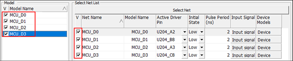
Figure 8. - Model Name: model name of the simulated and saved nets are listed.
- Copy: this menu enables the selected net(s) in the V column above to be registered at Select Net region for analysis.
- Linear: Network parameter will be solved for 300 frequency points
between 10 MHz ~ 5000 MHz.