Crosstalk Analysis
Crosstalk noise is the change in voltage and current caused on a signal line due to the signal switching of its neighborhood lines.
As the current wave propagates down the interconnection, an electric and a magnetic field are created. The electric field associated with the electric charge moving down the wire is responsible for the capacitive coupling of the wire with its adjacent wires. On the adjacent wires induced charges are also created. The magnetic field associated with the current in the interconnection which links through the loop formed by an adjacent wire and its return (ground) path is responsible for the inductive coupling. These two types of couplings not only result in current interference and voltage noise on adjacent wires but also result in distortion on the signal of the aggressor wire. The crosstalk noise on PCB depends on how close the routed traces are and how long the nearby parallel traces are. Thus, it is important to control the spacing among the signal traces and the maximum parallel length before and during routing.
Crosstalk Analysis menu allows you to analyze the crosstalk effect among closely coupled nets. Upon selecting the menu entire signal nets are listed. In certain degree entire nets in the PCB design have crosstalk coupling with each other. However, it is not only practical but also not necessary to analyze a lot of coupled nets together since crosstalk noise between far apart lines or short parallel lines is not significant. Separation amount and parallel line length are used as criteria for identifying closely coupled nets for the analysis. The crosstalk coupling control parameters include the maximum number of adjacent signal layers, maximum number of adjacent traces, minimum parallel trace length, maximum parallel via distance, and maximum parallel trace distance.
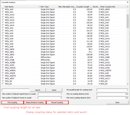
Figure 1.
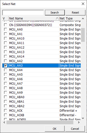
Figure 2.
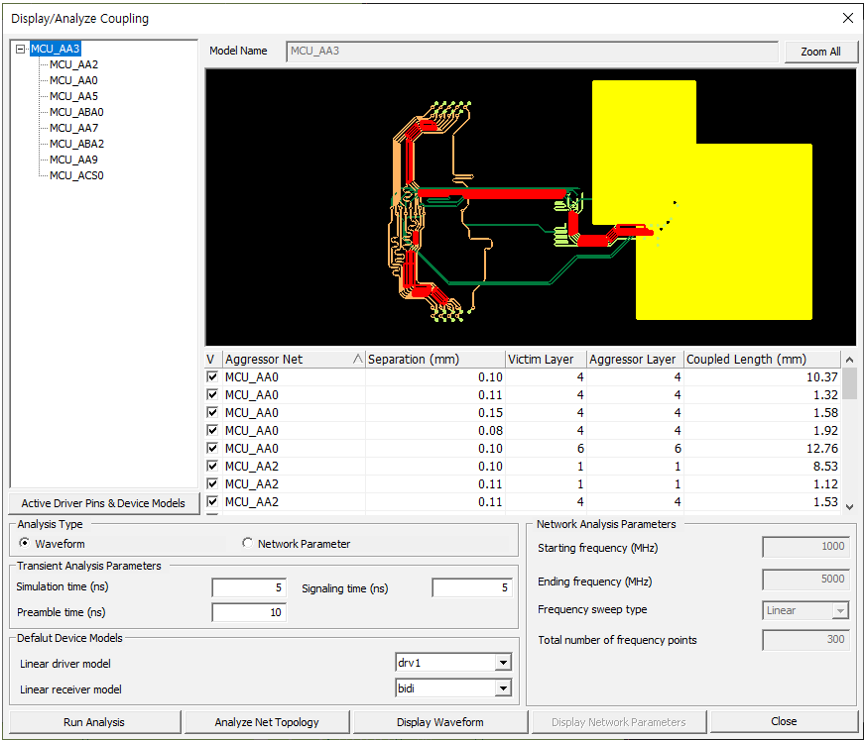
Figure 3.
Active Driver Pins menu allows you to select active driver pins of the coupled nets. To make a net quiet, NONE must be selected for the active driver pin selection. You can define the input signal and make changes on the device model selection for driver and receiver pins of each coupled net by clicking Input Signal and Device Models, respectively.

Figure 4.
From the menu bar, click to execute waveform and network parameter analysis for the selected net(s) considering the coupling effects by neighboring nets. When you specify the victim net, the strongly coupled nets are automatically screened through whole PCB layers. The coupling parasitic will be extracted and configured as SPICE circuit for the crosstalk analysis.
Depending on the selected victim net, the screened aggressor nets and victim net are automatically displayed for exploring the location. Several parameters in the Crosstalk Analysis Parameters laid in Electrical Analysis Constraints, will work to fine the mostly coupled nets to the selected victim net.