Automatic DDR BUS Analysis
Automatic DDR Bus Analysis menu is used for automatically extracting all data strobe, data, clock, address, command, and control line nets of DDR memory interfaces (using Net Class File), automatically constructing data line, address line, command line, and control line analysis models, performing eye diagram analyses on all the models, and calculating the setup and hold timing margins of all data, address, command, and control line signals.
menu enables you to analyze address/command/control group nets of DDR BUS in a one operation step.
Upon selecting the menu, existing automatic DDR bus analysis models are listed. Users can select a model to review the model or change the model and save as a new model.
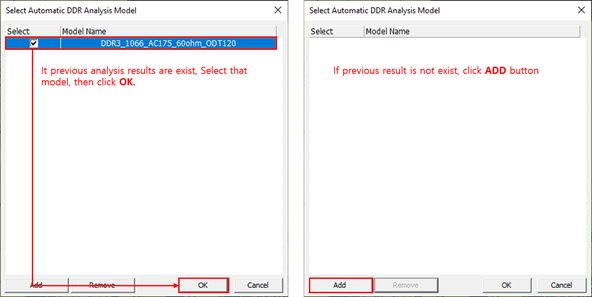
Figure 1.
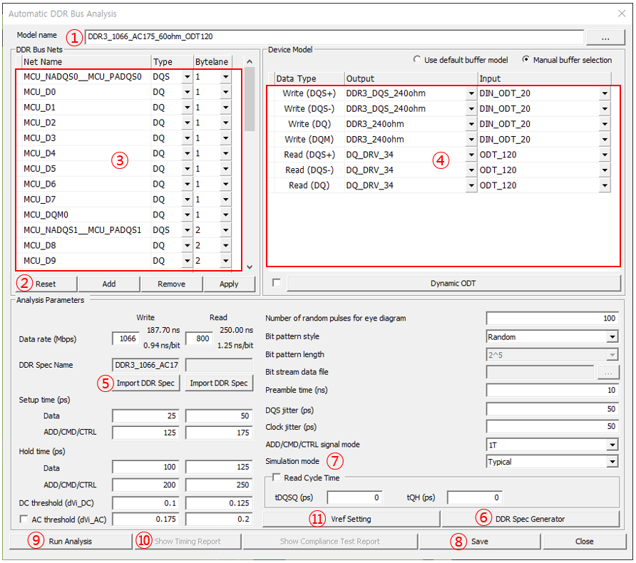
Figure 2.
Under DDR Bus Nets section, all automatically extracted DQS, DQ, CLK, ADD, CMD, and CTRL nets are listed. You should review the extracted net names and make corrections as needed by adding nets, removing nets, or changing the net types. For DQS and DQ nets correct byte lane numbers must be assigned.
When multiple device models are available, you must select device models of output and input pins of DQS+, DQS-, DQ, CLK, and ADD/CMD/CTRL nets, respectively. For the DQS and DQ nets, the device models must be selected separately for the data write and data read modes. Prior to running analysis, you can set the analysis control parameters which are identical to those of Data Line Analysis and ADD/CMD/CTRL Line Analysis.
You can bring in a DDR spec to use by selecting Import DDR Spec menu. You can also generate a new DDR spec in DDR Spec Generator after selecting the DDR Spec Generator menu.
You can select the simulation mode among Typical, Fast, and Slow. The simulation mode is applied to all device models used for the analysis.
- Extract Vref_DQ using analysis result: the tool automatically finds the V-reference voltage by measure using result waveform.
- Vref_DQ training result: you can type V-reference voltage value using V-reference training result.
The automatic DDR bus analysis models with analysis results are saved in DDR directory under Signal_Integrity of the PCB design project folder by selecting Save menu. The model name plus.DBM is used for the file name.
Upon selecting the Run Analysis menu, data line analysis and ADD/CMD/CTRL line analysis models are automatically constructed and analyses are automatically performed on all of the models.
Show Report menu allows you to review the timing margins of all DDR bus signals. For each signal, the report shows the data type, net name, output pin, input pin, timing margin Pass/Fail, setup margin, and hold margin. The data can be exported to an MS Excel file by selecting the Export to Excel menu.
The analysis results are automatically saved. The eye diagrams and timing margins of individual data line analysis and ADD/CMD/CTRL line analysis models can be viewed in Data Line Analysis and ADD/CMD/CTRL Line Analysis, respectively.
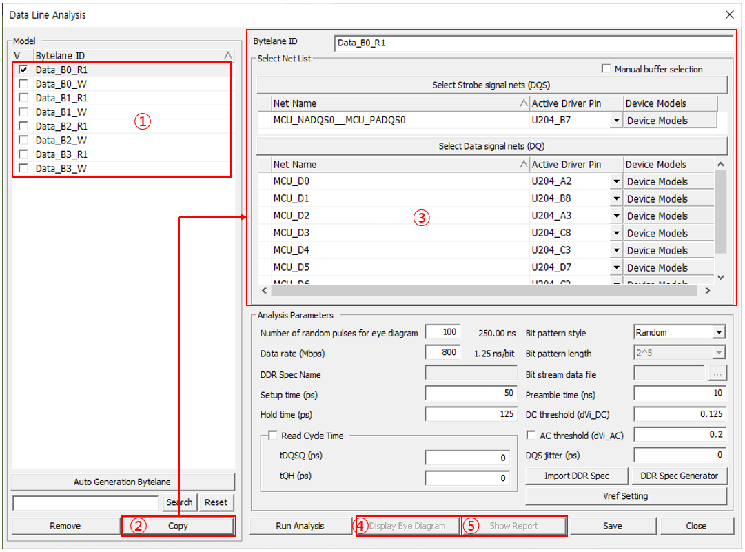
Figure 3.
Select each byte model and click Copy, all information is copied to nets field. You can review waveforms and timing margin by clicking Display Eye Diagram and Show Report.
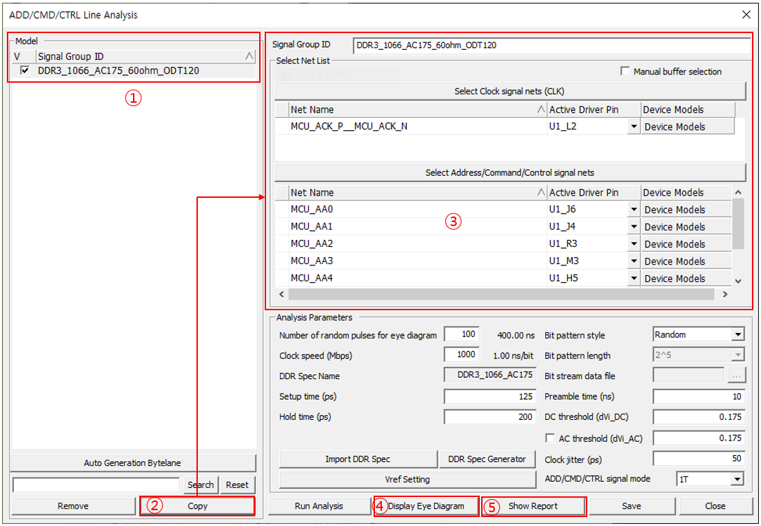
Figure 4.
Select each byte model and click Copy. All information is copied to nets field.
You can review waveforms and timing margin by clicking Display Eye Diagram and Show Report.