
Repairing Invalid CAD Parts
Use the Repair parts tool to heal invalid CAD parts after import.
- invalid topology
- invalid edge and vertex tolerances
- invalid geometry
- self-intersecting geometry
- non-G11 geometry
- missing edge or vertex geometry
- missing vertices
- vertices not on the curve of an edge
- edges and vertices not on the surface of face
-
After you import a CAD model, a message appears when invalid parts are
found.
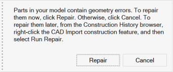
- To repair the geometry errors now, click Repair.
- Otherwise, click Cancel. To repair them later, from the Construction History browser, right-click the CAD Import construction feature, and then select Run Repair.
-
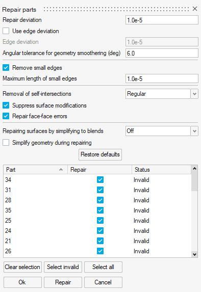
When you choose to repair, the Repair parts dialog box
appears.
The table lists Invalid parts, all of which are automatically selected for Repair.
-
In general, you can leave all parts selected, accept the default settings, and
then click the Repair button.
The status of healed parts changes to Valid.
-
If one or more parts are still Invalid, you can select
each individually, configure the settings, and then click the Repair
button.
Tip: To isolate an invalid part for closer inspection, select the part name in the table of the dialog box, and then press the I key.
- To accept the changes, click OK.
Adjusting CAD Repair Settings
For most cases, the default CAD repair settings will suffice. When modifying the
settings, a general rule of thumb is to use the smallest tolerance possible, or no
tolerance at all, if the option allows.
Note: Specified
tolerances are given in the model unit.
- Repair deviation
- The deviation between original and repaired geometry (the tolerance for repairing the part).
- Use edge deviation
- Turn on this option to enter the edge deviation.
- Edge deviation
- Turn on Use edge deviation, and then enter the deviation between original and repaired edges (the tolerance for repairing edges).
- Angular tolerance for geometry smoothening (degrees)
- The tangent angle change in degrees above which G1 discontinuities are removed by splitting topology rather than smoothening the geometry.
- Remove small edges
- Turn on this option to enter the Maximum length of small edges.
- Maximum length of small edges
- Turn on Remove small edges, and then enter the maximum arc length of edges to be removed.
- Removal of self-intersections
- Choose from the following options.
- Off: Turn off this setting.
- Regular: When a surface contains self-intersections located outside its face boundaries, then this portion of the surface will be removed by splitting the surface. This may result in the face being split into multiple faces.
- Advanced: A more in-depth algorithm is used to fix self-intersecting surfaces.
- Suppress surface modifications
- Surface geometry is preserved and repairs are confined to repairing face boundaries as far as possible.
- Repair face-face errors
- Attempt to repair face-face collisions in the body.
- Repairing surfaces by simplifying to blends
- Choose from the following options.
- Off: Turn off this setting.
- Each surface individually: Each surface is cleaned individually by simplifying to blends.
- Max surface chains: The maximum number of connected surfaces are cleaned by simplifying to blends.
- Simplify geometry during repairing
- Cleans and removes redundant topologies and geometries from the model during translation. Redundant vertices are deleted, and the associated edges are merged. Redundant edges are removed, and the associated faces merged.
1 A surface can be composed of several NURBS surfaces known as patches.
These patches should be fitted together in a way that the boundaries are
invisible. This is mathematically expressed by the concept of geometric
continuity. One of the options to establish geometric continuity is by means
of Tangential continuity (G1). It requires the end vectors of two curves or
surfaces to be parallel which eliminates sharp edges.