
Preferences: Inspire
Define preferences for mouse controls and options related to how information is calculated and displayed.
What's New
| Preference | Description |
|---|---|
| Show What's New dialog at startup | Select the checkbox to display a What's New dialog when the application starts. What's New highlights new features. |
Modeling Space
| Preference | Description |
|---|---|
| View projection | Select how to display 3D objects on a 2D plane:
|
| Front view | Select which plane to use as the front view. The default is -YZ. |
| Turntable rotation axis | Select which axis to use as the central axis for turntable rotation. The default is Z. |
| Show tooltips on parts | Select to show tooltips when hovering over parts in the modeling window. |
CAD Import Translator
Choose between a CT or Spatial reader.
By default, CATIA and STEP models use the Spatial reader because those file formats generally work best with Spatial. However, the quality of the translation is model-dependent. If you find your model is not reading cleanly into Inspire, please switch the translator in the preferences and reimport the model.
| Preference | Description |
|---|---|
| ACIS (.sab, .sat) | The default reader is CT. |
| CATIA V4 (.model) | The default reader is Spatial. |
| CATIA V5 (.CATPart, .CATProduct) | The default reader is Spatial. |
| IGES (.iges, .igs) | The default reader is CT. |
| Inventor (.ipt, .iam) | The default reader is CT. |
| PTC Creo (.asm, .prt) | The default reader is CT. |
| UG NX (Unigraphics) (.prt) | The default reader is CT. |
| SolidWorks (.sldprt, .sldasm) | The default reader is CT. |
| STEP (.step, .stp) | The default reader is Spatial. |
Geometry
| Preference | Description |
|---|---|
| Surface | Thickness: Define the default thickness used when creating surfaces. |
| Fillets | Radius: Define the default radius used when creating fillets. |
| Chamfers | Distance Angle: Define the default distance and angle
used when creating chamfers. Distance Distance: Define the default distance 1 and distance 2 values used when creating chamfers. |
| Part Replace | Auto Position: If Auto Position is enabled when doing part replacement, Inspire reads the internal transformation of the part within the CAD file to position the part within an assembly. If this option is turned off, it reads the part in where the part was created, generally (0,0,0). |
| Partition | Default Offset: Define the default offset used when creating partitions. |
| Parts | Select to maintain part orientation when moving to a new assembly. |
| Autofind | Select to automatically find features upon entering tools. |
| STL |
Export format: Select either ASCII or Binary as the export format for STL files. Export subdivision quality: Increase the level to create more triangles by splitting existing ones, maintaining the original geometry. |
| OBJ |
Import Format: Select whether to convert to PolyNURBS or mesh when importing OBJ files. |
| Import from CAD File | Fastest import:
Import hidden parts: Select Yes to import hidden parts that exist in some CAD formats like Catia V5. Note that importing hidden parts makes the import slower. Healing: When importing a CAD model, choose
how the application repairs geometry issues. Note: Healing
is not available when the Fastest import options,
Without diagnostics and With
diagnostics are turned on.
Split cylindrical faces: Enable this option to trim CAD cylinders on import. Combine points: Enable this option to combine points on import. Parasolid:
|
| Save to CAD format | Ignore deactivated parts: When saving a model as a
Parasolid, IGES, STEP, ACIS (.sat, .sab), STL, VRML, or Evolve (.pn) file, use
this option to indicate whether to include parts that have been deactivated. This
setting does not have an impact when saving as Inspire .imod
files. Save parts in current positions: Select the checkbox to save parts in their current positions without maintaining transformations relative to the assembly. This simplifies the model structure when you import the data into your CAD system. Parasolid export version: Select the version of Parasolid that Inspire exports to. By default, files are currently exported to 28.1. Default export format for Save Selected: Select the format to use when using the Save Selected command. Parasolid: Export tags: Enable this option to include tags when exporting Parasolid files. For more information, see Tags. |
| SimSolid: Face Faceting Parameters |
SimSolid uses lightweight facets to represent part faces. Assembly, part names, and hierarchy are retained. Default facet settings should be sufficient for most geometries, but adjustments can be made. The following faceting parameters are used to control tessellation:
|
| PDM (Product Data Management) | Select the check box to Check for updated parts at a regular interval as specified in the Timer (minutes) field. |
Implicit
| Preference | Description |
|---|---|
| Use GPU | Select the checkbox to use the computer's GPU (graphics processing unit) for implicit modeling. When the checkbox is not selected, calculations are performed on the CPU. |
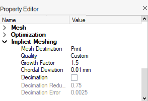
| Use Adaptive Remeshing |
When converting implicit parts to a mesh representation with one of the
remeshing options, a new remeshing algorithm has been implemented to create
adaptive meshes where the element size remains small near features and larger on
flatter regions.
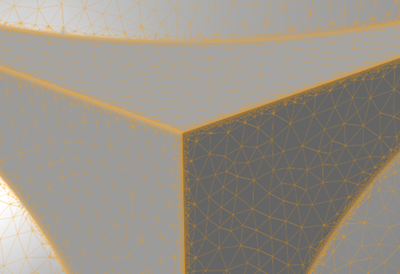 When the checkbox is enabled, the Growth Factor and
Chordal Deviation controls are available in the
Property Editor to control how remeshing is performed:
 |
Mouse Controls
| Preference | Description |
|---|---|
| Zoom Speed | Use to change the speed when zooming with the mouse. |
| Presets | This option defines the pan, view, and rotate controls assigned to the left
and right mouse buttons, so they are the same as used in another
application. Presets mouse controls for Inspire can be edited. To restore the preset values, click Use Defaults in the lower left corner of the Preferences window. |
Run Options
| Preference | Description |
|---|---|
| Run Options | Contact type for parts with fasteners: Select a contact type from the dropdown list to set the default contact type for parts with fasteners. Select No Contact to skip creating contacts, or select Sliding to create sliding contacts. Contact type for keep and find: Select a contact type from the dropdown list to set the contact type for disconnected parts in the Contact tool or when running analysis. This setting is also used with the Design Explorer. Select No Contact to skip creating contacts, or select Bonded. Gravity direction: When running an optimization or analysis, if the weight of a structure is a significant portion of the load it is bearing, then you should include gravity. By default, gravity pulls toward the negative z direction, but you can change the direction using the pull-down menu. Notify when run history exceeds size: Enable this option if you want Inspire to notify you when the run history exceeds the notification size specified in the field below. Run history notification size (MB): Specify a maximum size for the run history. If the run history exceeds this size, you will receive a notification if Notify when run history exceeds size is enabled. Analysis solver: Select whether to use SimSolid or OptiStruct as the solver for analysis. Run at model location: Enable this option if you want to store run history in the directory where the model is located rather than the run history path. Run history path: Specify the default location where run history is stored. |
| OptiStruct Solver Settings | Number of CPU cores: The number of CPU cores used
during optimization or analysis runs. For larger models, significant time savings
can be achieved by using at least two cores to perform the
calculation. Solution method: Select an OptiStruct
solver method.
Contact method: Select a contact type for
optimization calculations.
Memory allocated to the solver (MB): Specify a maximum size for memory allocated to the solver. |
| SimSolid | Save .stmod: Automatically save the files before
running SimSolid optimizations. Overlapping Parts Settings Check parts for overlaps before the run: Before running an optimization, automatically check parts for overlaps. Overlapping tolerance (mm): Define the minimum length of an overlap. |
| Analysis Legend Colors | Change the legend colors for each of the analysis result types. |
Materials
| Preference | Description |
|---|---|
| Default materials | Change the default material assigned to newly created parts. |
| Show Inspire standard materials | Inspire includes a standard material library that can be accessed from the Parts and Materials table or the right-click context menu. Deselect this option to disable the standard material library. (You must designate a custom material library under My Standard Materials first.) |
| My standard materials | Designate your own custom material library. Click the Value field and then browse to a material file. |
Visualization
| Preference | Description |
|---|---|
| Visualization | Tessellation edge deviation: The maximum distance
allowed between the edge and the geometry used to approximate it for rendering. A
smaller deviation will result in better graphical quality but slower system
performance. Tessellation surface deviation: The maximum distance allowed between the surface and the geometry used to approximate it for rendering. A smaller deviation will result in better graphical quality but slower system performance. Enable fading effects: Select this option to make a part slowly fade away when you hide it. We recommend that you deselect this option when working with large assemblies to improve performance. Show section cuts in part color: Show section cuts in the same color as the parts. Load labels: Select which constraint types
are visible in the modeling window.
|
| View Cube | Show view cube: Define when the View Cube is visible
in the modeling window. Position: Define the position of
the View Cube in the modeling window.
Show axis arrows: Display the x-, y-, and z-axes on the View Cube. Geometry: Define the View
Cube's shape.
Show View Cube rotators: Define when the View
Cube rotators are visible in the modeling window.
Show View Cube reflectors: Define when the
View Cube reflectors are visible in the modeling window.
Increment angle: Define by how many degrees left- and right-clicking the arrows incrementally rotates the view. By default, left- and right-clicking increments by + and - 15 degrees. |
Sketching
| Preference | Description |
|---|---|
| Snap to grid | Enabled by default, this function allows you to snap objects to a grid as you sketch curves or translate parts. Deselect the check box to turn snapping off. |
| Snap to visible grid only | Restrict snapping to visible grids only. |
| Make sketch plane normal to the view | Enable this option if, when sketching on a part, you want Inspire to automatically rotate the part so that the sketch plane is normal to the view. If you want to maintain a true view of the sketch plane, deselect this option. |
| Auto apply constraints | Sketch constraints are specific limitations or restrictions that can be placed on sketch curves. Some sketch entities are created with sketch constraints automatically applied, like perpendicular angles for rectangles. Disable this option to stop the automatic application of constraints when sketching. |
| Auto apply constraints after using the Break tool | By default, sketch constraints are automatically applied after using the Break tool. Disable this option to stop the automatic application of constraints when using this tool. |
| Define auto tangent angle | When joining lines and arcs, a tangent constraint is automatically applied if the line and arc are nearly tangent. Use this option to define how far, in degrees, the line and arc can deviate from a straight line and still have the constraint applied. |
| Define auto perpendicular angle | When joining lines, a perpendicular constraint is automatically applied if the lines are nearly perpendicular. Use this option to define how far, in degrees, the lines can deviate from perpendicular and still have the constraint applied. |
| Define auto horizontal vertical angle | When sketching line segments, a horizontal or vertical constraint is automatically applied if the line segment is nearly aligned with the grid. Use this option to define how far, in degrees, the line segment can deviate from the grid and still have the constraint applied. |
| Grid spacing | Inspire has five progressive levels of grid spacing. To change the default spacing for a particular grid, enter a value in the Grid spacing text box. Grid spacing for metric and English unit systems are maintained separately. (See numbers and units.) Click Use Defaults to restore the default values. |
Mass Calculation
| Preference | Description |
|---|---|
| Mass calculation | Right-click the column header in the Model Browser and select Mass to view masses. To improve overall performance, when a CAD file is imported the mass sizes are not calculated and are shown as ** in the Model Browser. Click the Calculate button to display the mass. |
Move Tool
| Preference | Description |
|---|---|
| Free Move: Show angles when editing tool position | By default only the X, Y, Z coordinates of the Move tool origin are shown in the microdialog. If this preference is selected, the angles are shown as well when editing the tool position. |
Collision Detection
| Preference | Description |
|---|---|
| Check for collisions | Define whether Inspire should check for collisions between all parts, no parts, or only parts that specifically have collision detection applied. |
Units
| Preference | Description |
|---|---|
| Model units | Change the unit system used for calculations for Motion analysis. All structural analysis and optimization runs use MKS units. To run structural analysis or optimization in different units, export the preferred units and run manually. |
| Display units | Change the unit system used in the user interface. |
Number Format
| Preference | Description |
|---|---|
| Modeling | Format type: Choose a format type for displaying
decimals in value fields: “Scientific” notation or “Mixed” (either fixed decimal
or scientific form, whatever is the shortest). Remain in fixed format between: Show in the fixed form when within the selected range. Otherwise, show in the scientific form. Precision: Choose the number of decimal places displayed in value fields. Remove trailing zeros: Remove all but one zero after the decimal point in value fields. |
| Results | Format type: Choose a format type for displaying
decimals in value fields: ”Legacy” (use the same number format that was used in
version 2022.1 or earlier), “Scientific” notation, or “Mixed” (either fixed or
scientific form, whatever is the shortest). Precision: Choose the number of decimal places displayed in the Analysis Explorer results slider. Remove trailing zeros: Remove all but one zero after the decimal point in the Analysis Explorer results slider. |